Manipulator Dynamics
Manipulator Dynamics. Amirkabir University of Technology Computer Engineering & Information Technology Department. Introduction. Robot arm dynamics deals with the mathematical formulations of the equations of robot arm motion. They are useful as:


Manipulator Dynamics
E N D
Presentation Transcript
Manipulator Dynamics Amirkabir University of TechnologyComputer Engineering & Information Technology Department
Introduction • Robot arm dynamics deals with the mathematical formulations of the equations of robot arm motion. • They are useful as: • An insight into the structure of the robot system. • A basis for model based control systems. • A basis for computer simulations.
Equations of Motion • The way in which the motion of the manipulator arises from torques applied by the actuators, or from external forces applied to the manipulator.
Forward and Inverse Dynamics Given a trajectory point, and find the required vectors of joint torques, Given a torque vector, calculate the resulting motion of the manipulator, and : problem of controlling the manipulator : problem of simulating the manipulator
Two Approaches • Energy based: Lagrange-Euler. Simple and symmetric. • Momentum/force approach:Newton-Euler. Efficient, derivation is simple but messy, involves vector cross product. Allow real time control.
Newton-Euler Algorithm • Newton-Euler method is described briefly below. The goal is to provide a big picture understanding of these methods without getting lost in the details.
Newton-Euler Algorithm Newton-Euler formulations makes two passes over the links of manipulator Velocities, Accelerations Forces, moments Gravity
Newton-Euler Algorithm • Forward computation • First compute the angular velocity, angular acceleration, linear velocity, linear acceleration of each link in terms of its preceding link. • These values can be computed in recursive manner, starting from the first moving link and ending at the end-effector link. • The initial conditions for the base link will make the initial velocity and acceleration values to zero.
Newton-Euler Algorithm • Backward computation • Once the velocities and accelerations of the links are found, the joint forces can be computed one link at a time starting from the end-effector link and ending at the base link.
Acceleration of a Rigid Body Linear and angular accelerations:
Linear Acceleration : origins are coincident. : re-write it as. : by differentiating.
Linear Acceleration the case in which the origins are not coincident : when is constant : the linear acceleration of the links of a manipulator with rotational joints.
Angular Acceleration B is rotation relative to A and C is rotating relative to B : the angular acceleration of the links of a manipulator.
Inertia • If a force acts of a body, the body will accelerate. The ratio of the applied force to the resulting acceleration is the inertia (or mass) of the body. • If a torque acts on a body that can rotate freely about some axis, the body will undergo an angular acceleration. The ratio of the applied torque to the resulting angular acceleration is the rotational inertia of the body. It depends not only on the mass of the body, but also on how that mass is distributed with respect to the axis.
Mass Distribution Inertia tensor- a generalization of the scalar moment of inertia of an object
Moment of Inertia The moment of inertia of a solid body with density w.r.t. a given axis is defined by the volume integral where r is the perpendicular distance from the axis of rotation.
Moment of Inertia This can be broken into components as: for a discrete distribution of mass for a continuous distribution of mass
Moment of Inertia The inertia tensor relative to frame {A}: Mass moments of inertia Mass products of inertia
Moment of Inertia • If we are free to choose the orientation of the reference frame, it is possible to cause the products of inertia to be zero. • Principal axes. • Principal moments of inertia.
Example 6.1 {C}
Parallel Axis Theorem • Relates the inertia tensor in a frame with origin at the center of mass to the inertia tensor w.r.t. another reference frame.
Measuring the Moment of Inertia of a Link • Most manipulators have links whose geometry and composition are somewhat complex. A pragmatic option is to measure the moment of inertia of each link using an inertia pendulum. • If a body suspended by a rod is given a small twist about the axis of suspension, it will oscillate with angular harmonic motion, the period of which is given by. where k is the torsion constant of the suspending rod , i.e., the constant ratio between the restoring torque and the angular displacement.
Newton’s Equation Force causing the acceleration
Euler’s Equation Moment causing the rotation
Iterative Newton-Euler Dynamic Formulation • Outward iterations to compute velocities and accelerations • The force and torque acting on a link • Inward iterations to compute forces and torques
Force Balance Using result of force and torque balance: In iterative form:
The Iterative Newton-Euler Dynamics Algorithm 1st step: Link velocities and accelerations are iteratively computed from link 1 out to link n and the Newton-Euler equations are applied to each link. 2nd step: Forces and torques of iteration and joint actuator torques are computed recursively from link n back to link 1.
Inclusion of Gravity Forces • The effect of gravity loading on the links can be included by setting , where G is the gravity vector.
The Structure of the Manipulator Dynamic Equations : state space equation : mass matrix : centrifugal and Coriolis terms : gravity terms : configuration space : matrix of Coriolis coefficients : centrifugal coefficients
Coriolis Force • A fictitious force exerted on a body when it moves in a rotating reference frame.
Lagrangian Formulation of Manipulator Dynamics • An energy-based approach (N-E: a force balance approach) • N-E and Lagrangian formulation will give the same equations of motion.
Kinetic and Potential Energy of a Manipulator Total kinetic energy of a manipulator Total potential energy of a manipulator
Lagrangian • Is the difference between the kineticand potential energy of a mechanical system
The equations of motion for the manipulator vector of actuator torque
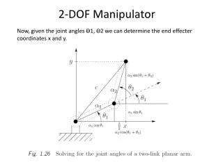
Example 6.5 : variable The center of mass of link 1 and link 2
Manipulator Dynamics in Cartesian Space Joint space formulation Cartesian space formulation
The Cartesian configuration space torque equation: :Coriolis coefficients :Centrifugal coefficients
Dynamic Simulation: (Euler Integration) Simulation requires solving the dynamic equation for acceleration Nonrigid body effects: friction : Given initial conditions We apply numerical integration to compute positions and velocities:
Next Course: Trajectory Generation Amirkabir University of TechnologyComputer Engineering & Information Technology Department