Download
1 / 21
220 likes | 257 Views
Learn about thin film interference, diffraction gratings, crystal diffraction, Rayleigh's criterion, and applications such as spectrographs and telescope resolution. Explore examples and understand how diffraction limits optical equipment.

E N D
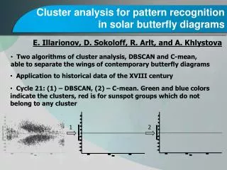
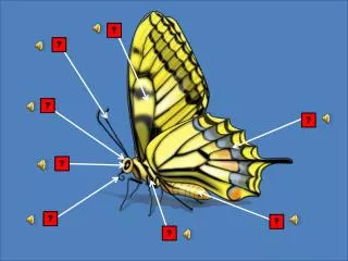
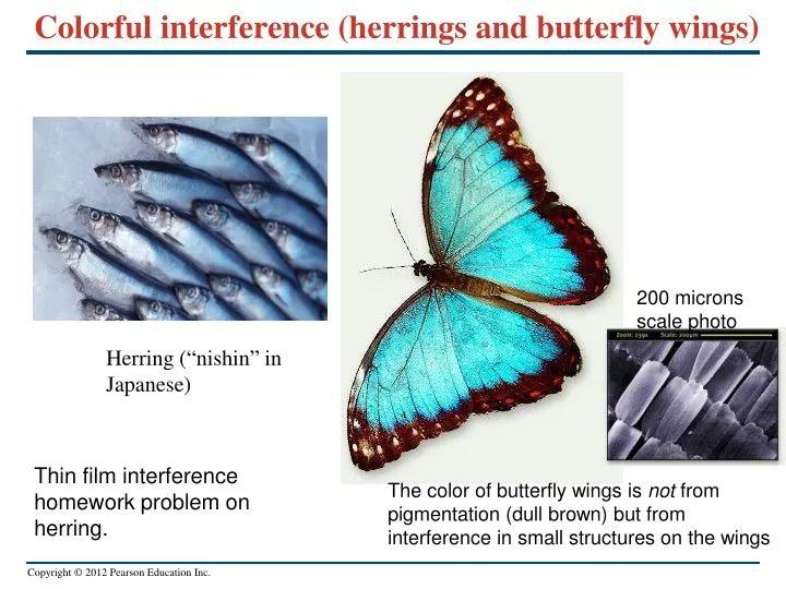
Colorful interference (herrings and butterfly wings) 200 microns scale photo Herring (“nishin” in Japanese) Thin film interference homework problem on herring. The color of butterfly wings is not from pigmentation (dull brown) but from interference in small structures on the wings
Last time: Interference pattern of several slits • The figure below shows the interference pattern for 2, 8, and 16 equally spaced narrow slits. If there are N slits, how many minima in the diffraction pattern between the maxima ? Ans: N-1 Width ~1/N to conserve energy The height of each maxima is proportional to N2. So what does this mean for the width ?
Today • Diffraction grating • Diffraction limit and Rayleigh criterion. • Crystal Diffraction. • Next time: Holography, review of diffraction (Chap 36)
The diffraction grating • A diffraction grating is an array of a large number of slits having the same width and equal spacing. The intensity maxima occur at Looks similar to equations, be careful • Some points to note: • d is the spacing between slits • The angle θ is the angle between the center of the slit array to the mth bright region on the screen.
Diagram of a grating spectrograph • A diagram of a diffraction-grating spectrograph for use in astronomy. Chromatic resolving power
Grating spectrographs • A diffraction grating can be used to disperse light into a spectrum. • The greater the number of slits, the better the resolution. • Figure 36.18(a) below shows our sun in visible light, and in (b) dispersed into a spectrum by a diffraction grating. See description of Eschelle spectrograph: http://www.vikdhillon.staff.shef.ac.uk/teaching/phy217/instruments/phy217_inst_echelle.html
Interesting diffraction grating example • The intensity maxima for a diffaction grating occur at • An astronomer examining a distant galaxy observes a line in the hydrogen spectrum that has a wavelength of 656.3 nm (Hα line) in first order. Using a transmission diffraction grating 5758 lines/cm she finds that the bright fringe for the Hα occur at ±23.410 from the central spot. How fast is the galaxy moving ? Why is the line shifted ? Ans: Doppler effect
Example of a diffraction grating • The intensity maxima for a diffaction grating occur at • Example 36.4: The wavelengths of the visible spectrum are approximately 380 nm (violet) to 750 nm (red). (a) Find the angular limits of the first-order visible spectrum produced by a plane grating with 600 slits per millimeter when white light falls normally on the grating. (b) Do the first order and second order spectra overlap? What about the 2nd and 3rd orders? • (a) distance between slits is • Violet light for 1st order occurs at • Red light for 1st order occurs at • (b) recalculate for m = 2 and m = 3. The 2nd-order spectrum extends from 27.1-63.9° while the 3rd order is from 43-90. Yes there is overlap
Airy disk (circular aperture) What is different about this diffraction pattern ? Ans: It is produced by a circular aperture and has rings
Circular apertures • An aperture of any shape forms a diffraction pattern. • The figures below illustrate diffraction by a circular aperture. The Airy disk is the central bright spot. • The first dark ring occurs at an angle given by sinθ1 = 1.22 λ/D.
Diffraction and image formation • Diffraction limits the resolution of optical equipment, such as telescopes. • The larger the aperture, the better the resolution. The figure on the right illustrates this effect. However, in practice the atmosphere provides a more stringent limit than diffraction
Summary of Diffraction Limit (Rayleigh’s criterion) Angular radius of the first dark ring in the circular diffraction pattern Rayleigh criterion for the diffraction limit Lord Rayleigh 1904 Nobel Prize in Physics Idea: center of one diffraction pattern coincides with the first minimum of the other. (Note that D is the diameter of the aperture for a lens or telescope.)
Bigger telescope, better resolution • Because of diffraction, large-diameter telescopes, such as the VLA (Very Large Array) radio telescope in New Mexico below, give sharper images than small ones. • 27 telescopes, 25m in diameter effective aperture 36 km ! Rayleigh criterion gives (λ=1.5cm, D=36 km) 5 x 10⁻⁷ rad
Sites for the SKA (Square Kilometer Array) The effective area will be 3000 km when completed (sites on every continent except South America)
Crystal Diffraction Basics • Can we observe crystal diffraction with visible or ultraviolet light ? (Hint: what is the typical spacing of the components of a crystal.) Ans: No, for example the wavelength of visible light is 400-700 nm, but the plane spacing in NaCl is 0.28nm. UV is 100nm to 380nm so that won’t work either. How can we observe crystal diffraction and understand the atomic structure of a crystal (or a protein) ? Ans: use coherent x-rays
X-ray diffraction • When x rays pass through a crystal, the crystal behaves like a diffraction grating, causing x-ray diffraction. The figure below illustrates this phenomenon. A version of this experiment is done at UH in PHYS481L.
A simple model of x-ray diffraction The Bragg condition for constructive interference is 2d sinθ = mλ The path difference is the due to the dimensions of the crystals (reflected x-rays have slightly different path lengths)
A simple model of x-ray diffraction The Bragg condition for constructive interference is 2d sinθ = mλ
An example of holography • Photographs of a holographic image from two different angles, showing the changing perspective.
What is holography? • By using a beam splitter and mirrors, coherent laser light illuminates an object from different perspectives. Interference effects provide the depth that makes a three-dimensional image from two-dimensional views.
How does holography work? • Follow the analysis using the Figure below.