Download
1 / 296
2.96k likes | 2.98k Views
Explore network types, topologies, protocols, physical issues, and layered network architectures. Delve into internet history and assignments using tools like Wireshark. Gain insights into LAN, PAN, MAN, WAN, and internet connections.

E N D
CA169Networks & Internet Lecturer & Co-ordinator Brian.Stone@DCU.IE
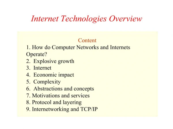
Layered Network Architectures. History of the Internet Physical Issues, Data Encoding, etc.. The Data-Link Layer The 802 protocols Wired & Wireless Networks The Web Network Devices Communications Protocols Local area networks (data link layer) Internet Protocols Tying together MAC, IP and TCP addressing and introducing URLs Network tools The Course (indicitive)
Indicative Assignments and Lab work • Generating HTML for the Web • Networking tools – Using Wireshark • Wireshark traffic capture and analysis exercises (several) • Web browsers • Moodle quizzes • Network survey
Course Structure • This course • Small timetabling differences later in semester • Exam worth 50% • Assignments worth 50% • Repeats possible for assessments and exams. • 2 lectures per week (for now) • Labs on occasions (some online) • Moodle for distributing notes and collecting assignments.
Lecture Notes CA169
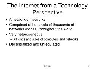
What is a network? • Two or more computers linked together to share resources • Share files, printers, electronic communication etc. • Linked through cables, telephone lines, radio waves, satellites or infrared beams. • Four basic types of networks • Local Area Network (LAN) • Personal Area Networks (PAN) • Metropolitan Area Network (MAN) • Wide Area Network (WAN)
Local Area Network • Network confined to a relatively small geographic area. Typically lab in CA, office etc. • Typical LAN has a central server which controls the network. Can share resources ….printers, files. Should be more powerful than the clients.
PAN • Tends to be wireless WPAN • Phone talking to organiser or Internet • May be carried over • Ethernet • WiFi • NFC • IR • Bluetooth • ZigBee
Metropolitan Area Network • Covers larger geographic areas, cities, schools, local libraries, government offices • Typically uses dedicated phone lines, coaxial cabling, fibre optic cable and wireless communication
Wide Area Network • Connects larger geographic areas, such as global companies. Local and global networks are connected to form larger network. • Typically uses transoceanic or satellite links • Protocols used can be ATM networks or MPLS (carrying Ethernet) or others. • Typically use special hardware and special fibres. • Physical layer can be DWDM
The Internet • All of the previous network types can connect to the internet • Infrastructure software needed – TCP\IP • Global services available through Internet • Internet aware applications • Network aware devices • The Internet has transformed the way we do things!
Network Topologies • Topology is how the cables, computers and other peripherals are connected • Different types of topologies • Star • Ring • Bus • Tree • Complete • Irregular
Bus Topology (2) • Computers share the same bus (cable) with a terminator at each end. Each client is connected to the bus. • Old Ethernet on coaxial cable utilises a bus • Simple and reliable, not much hardware needed. • Inexpensive cable and easy to expand • Uses the least cable • Management more problematic • Heavy traffic slows overall throughput • A break in network brings whole thing down. Can be difficult to detect.
Star Topology Switch Check out the cabinets in our labs.
Star Topology (2) • Each node connected directly to central computer. All data must go through central node (hub/switch) • Relies heavily on central computer • Each device has a separate wire. Easy to install new devices. Disconnecting / Adding devices does not interrupt network. Easy to detect breaks/faults • More cable is required (look at our cabinets) • If central node fails, network falls over • Commonly uses twisted pair, also uses co-axial (rare now) cable and fibre optics
Ring Topology (2) • Computers tied together in a ring • Each device is connected to the next one in line • Circle of cable • Signal travels in one direction • When a device receives control (token) • It acts on it • or passes it on • Not common these days for LAN.
Modern LANs utilise Switches to build a tree topology, even when the network looks like a mesh. Need to ensure that loops are not introduced, special protocols built into switches (STP) Tree Topology
Topology Considerations • Money • Bus cheapest, no need for central node • But what about management cost? • Length of cable • Bus uses shortest cable, but how expensive is cable anyhow? • Efficiency • Star topology easies to add new nodes • Manage existing infrastructure • Cable type • Most common cable is twisted pair, most often used with star topologies
Network Architecture Need to break down idea of a network into easily understood abstractions – use layered architecture
Layered Architectures • The ISO defines a 7 layer Architecture. • TCP\IP is defined as a 4 layer Architecture. • ISO is a prescriptive Architecture • TCP\IP is descriptive.
Application Application 7 7 Presentation Presentation 6 6 Session Session 5 5 Transport Transport 4 4 Network Network 3 3 Data Link Data Link 2 2 Physical Physical 1 1 Physical Network OSI Model
OSI (2) 7. Application Layer (Top Layer) 6. Presentation Layer 5. Session Layer 4. Transport Layer 3. Network Layer 2. Data Link Layer 1. Physical Layer (Bottom Layer)
OSI (3) • The Applicationlayer represents the level at which applications access network services. This layer represents the services that directly support applications such as software for file transfers, database access, and electronic mail. • The Presentationlayertranslates data from the Application layer into an intermediary format. This layer also manages security issues by providing services such as data encryption, and compresses data so that fewer bits need to be transferred on the network. • The Session layerallows two applications on different computers to establish, use, and end a session. This layer establishes dialog control between the two computers in a session, regulating which side transmits, plus when and how long it transmits.
OSI (4) • The Transport layer handles error recognition and recovery. It also repackages long messages when necessary into small packets for transmission and, at the receiving end, rebuilds packets into the original message. The receiving Transport layer also sends receipt acknowledgments. • The Network layer addresses messages and translates logical addresses and names into physical addresses. It also determines the route from the source to the destination computer and manages traffic problems, such as switching, routing, and controlling the congestion of data packets. • The Data Link layer packages raw bits from the Physical layer into frames (logical, structured packets for data). This layer is responsible for transferring frames from one computer to another, without errors. After sending a frame, it waits for an acknowledgment from the receiving computer.
OSI (5) • The Physical layertransmits bits from one computer to another and regulates the transmission of a stream of bits over a physical medium. This layer defines how the cable is attached to the network adapter and what transmission technique is used to send data over the cable.
TCP/IP OSI Application Application 7 Presentation 6 Session 5 5 Transport Transport 4 4 Internet Protocol Network 3 3 Network Interface Transport Data Link 2 2 Physical Physical 1 1 TCP/IP & OSI
TCP/IP & OSI (2) • The OSI model is the seven layer Open Systems Interconnection model. It was developed to serve as a standard model for network architectures. Transmission Control Protocol / Internet Protocol (TCP/IP) is the protocol on which the Internet is based upon. It has five layers and they are related to the OSI model as above. • Information is transmitted around the Internet in packets. These packets contain among other things the destination and source addresses of the packet and the data. The protocol used is TCP/IP. Internet Protocol is protocol, which sends packets around the Internet. TCP sits on top of IP and it guarantees reliable delivery of packets for applications such as FTP and Telnet. An end-to-end connection is open for the delivery session between two applications.
Meet Some of the TCP/IP Family FTP SMTP SNMP Telnet 1 2 3 4 TCP UDP IP 802.11WiFi 802.3 LAN Arpanet
Why Two Models • OSI concepts • Services (definition) • Interfaces (how to access) • Protocols (peer protocols, private) • Kind of OO approach, encapsulation. • Prescriptive & Descriptive origins • Simple services, interfaces, protocols
Why Two Models (cont.) • Bad Timing • Apocalypse of Two elephants (research & investment) • Bad technology. • Copying proprietary SNA. • Empty layers. • Cross a mobster with a standard… • you get made an offer that you cannot understand.
Physical Layer Host-to-Network Layer of TCP/IP
Physical Layer Issues • Attenuation & Data Rates. • Nyquest’s Theorem • Max rate = 2H bps (H is bandwidth in Hz) • Shannon’s Theorem • Max rate = H log2 (1 + S/N) bps • Shannon takes noise into account.
Coaxial Cable • Like your TV cable at home • Single copper conductor at centre with plastic layer providing insulation between conductor and braided metal shield. Shield prevents interference • Supports longer cable length the UTP • Thin coaxial (10Base2) • Max segment length 185M • Thick coaxial (10Base5) • Max segment length 500M
Coaxial Cable BNC Connector Coaxial Cable (2)
Unshielded Twisted Pair • Cable has 4 pairs of wires, twisted in pairs • UTP can be telephone grade to high-speed cable • 5 categories • 1 voice only • 2 Data up to 4 Mbps • 3 Data up to 10 Mbps • 4 Data up to 20 Mbps • 5 Data up to 100 Mbps • Can be susceptible to radio and electrical interference. Shielded Twisted Pair exists, but extra shielding makes it bulky
Unshielded twistedpair RJ-45 Connector Unshielded Twisted Pair (2)
Fibre Optic Cable Fibre Optic • Centre glass core surrounded by layers of protection • Transmits light rather than electrical signals Not susceptible to electrical interference • Capable of transmitting data over longer distances and at higher speeds than coaxial and TP • 10BaseF • Outer coating is made from Teflon or PVC • Plastic helps cushion glass core • Kevlar around plastic strengthens cable and prevents breakage
Security and Fibre Networks • From a security perspective, one of the great advantages of fibre networks is that they do not radiate any electromagnetic signals • There is a prevalent myth that fibre networks cannot be tapped: with physical access to the cable, they can • However, it is considered impossible to tap an optical cable without introducing a detectable increase in attenuation. A secure system should continuously monitor received optical signal strength and should alert on any abrupt change
Connectors • SC – In widespread use. Used on the original Gigabit Ethernet GBICs • LC – Used in newer cabling installations. Used on new small form factor (SFP) GBICs • ST – “Bayonet” mount, often used on older fibre installations
Connectors • FC – Screw mount. Only ever found on carrier-grade equipment (and usually with higher-powered lasers…don’t look into these)
Patch Panels • Fibre within or between buildings are typically terminated on patch panels like these • Fibre patch cables are used to link active equipment to the patch panels
Patch Panels • In order to ensure that Transmit is always connected to Receive in each direction, patch leads and internal cable plant are always (supposed to be) crossed over • This means that you can use a patch cable on its own to link two physically adjacent devices
Laser Safety • Lasers are categorised into various classes according to the amount of optical power they emit. It is important to know what these mean:-
Laser Safety • In “enterprise” communications equipment, lasers more powerful than Class1 are rarely encountered (but always check !). • Class 3 lasers are sometimes encountered in long-haul, DWDM carrier networks.
Radio • Wireless LAN • No cables • High frequency radio signals • Each workstation has a transceiver / antenna • Also includes mobile phone technology, microwave transmission, satellite for longer distances • Expensive, history of poor security (now down to ignorance, strong encryption available now), • Susceptible to interference • More on this later