Download
1 / 19
190 likes | 313 Views
Commissioning of the CMS Electromagnetic Calorimeter and Operational Experience. CALOR 2006 Chicago, June 5 th – 9 th , 2006. Paolo Rumerio, CERN On behalf of the CMS Electromagnetic Calorimeter Group. Outline. The Barrel electromagnetic calorimeter (ECAL) of CMS Electronic system

E N D
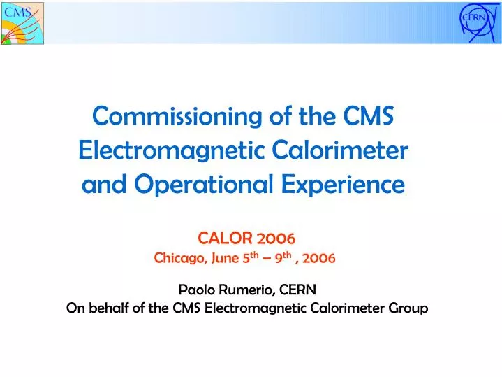
Commissioning of the CMSElectromagnetic Calorimeterand Operational Experience CALOR 2006 Chicago, June 5th – 9th , 2006 Paolo Rumerio, CERN On behalf of the CMS Electromagnetic Calorimeter Group
Outline • The Barrel electromagnetic calorimeter (ECAL) of CMS • Electronic system • Installation of the on-detector electronics • Commissioning and operation of the detector • Current status and plan • Conclusions Paolo Rumerio, CERN CALOR 2006 Page 2
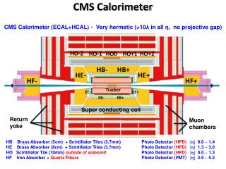
The ECAL Barrel Detector of CMS • The CMS electromagnetic calorimeter (ECAL) is a compact detector designed to operate in a challenging environment: • 4T magnetic field • high radiation environment of 1-2 kGy/year • at the LHC bunch crossing rate of 40 MHz. • The Barrel part of ECAL consists of 61,200 lead-tungstate (PbWO4) crystals optically coupled to twice as many Avalanche Photodiodes (APD): • short radiation length of 8.9 mm and small Moliere radius of 22 mm • fast scintillator • radiation-hard (do need monitoring of transparency → see A. Bornheim’s talk) • The radiation-tolerant, on-detector electronics performs several of the data acquisition functions. It comprises: • ~ 20,000 printed circuit boards • ~ 5000 optical links. Paolo Rumerio, CERN CALOR 2006 Page 3
ECAL Barrel Construction A super-module • At two regional centers, CERN and INFN/ENEA Rome: • crystals are characterized • coupled to APDs • assembled into modules (400 or 500 crystals/module) • → see R. Paramatti’s talk. 2 APDs/crystal At CERN, each set of 4 modules is made into a super-module, completed with cooling system. There are 36 super-modules in ECAL Barrel, each of them has 1700 crystals. Paolo Rumerio, CERN CALOR 2006 Page 4
VFE x 5 FE Front End card (FE) MB Trigger Sums LVR Data Trigger Tower (TT) Very Front End card (VFE) On-detector Electronics • Modularity: Trigger Tower – it reads a 5x5 grid of crystals: • 5 VFEs (Very Front End cards) - each one reads a strip of 5 crystals along φ • 1 FE (Front End card) – it controls and receives data from the 5 VFEs • 1 LVR (Low Voltage Regulator card) – it stabilizes and distributes the LV • 1 MB (Mother Board) – it distributes the HV and provides connections to the VFEs. • On the FE: • 2 GOHs (Gigabit Optical Hybrids) – to send out data and trigger primitives • 1 CCU (Clock & Control Unit) – I2C interface. • The 68 FEs on a super-module are connected by a system of 8 Token Rings. Paolo Rumerio, CERN CALOR 2006 Page 5
HV 2 x12 12 bits Logic 1 x6 12bitADC 2 bits 0 MGPA x1 APD VFE architecture for single channel On-detector Electronics • On a VFEs, each one of the 5 crystal signals: • is amplified by a Multiple Gain Pre-Amplifier (MGPA) with 3 gains (1, 6 and 12) • the 3 outputs are digitized in parallel by 3 of the 4 channels of a 40-MHz, 12-bit ADC • the highest, non-saturated gain is selected by a digital logic VFE • The FE: • stores data during the Level 1 trigger latency of about 3μs • prepares and sends trigger primitives at a 40-MHz rate. Paolo Rumerio, CERN CALOR 2006 Page 6
Clock & Control System (CCS) Trigger Concentrator Card (TCC) Data Concentrator Card (DCC) Off-detector Electronics Modularity: 1 super-module Selective Readout Process • Main functions of the off-detector electronic boards: • CCS: reception/distribution of LHC clock and control signals + front-end initialization • TCC: encoding of trigger primitives and transmission to Regional Calorimeter Trigger at 40 MHz + classification of trigger tower importance and transmission to SRP at Level 1 rate • DCC: integrity check + data reduction + transmission to central DAQ at Level 1 rate Paolo Rumerio, CERN CALOR 2006 Page 7
Electronics Integration Center The on-detector electronics is installed and tested at CERN Prevessin Paolo Rumerio, CERN CALOR 2006 Page 8
On-detector Electronics Installation • The installation of the on-detector electronics proceeds as follows: • Motherboards are installed and connectivity verified. • VFE, LVR and FE cards are installed • Each trigger tower is fully tested before proceeding with the next one • Token Rings are installed. Default and redundancy connection paths are tested. • Trigger and data optical links (GOHs), and Distributed Fiber Patch Panels are connected • Trigger towers are re-tested with their final links. • Low Voltage Distributors are installed and voltage outputs measured. Paolo Rumerio, CERN CALOR 2006 Page 9
Single Trigger Tower Test • Each trigger tower is connected and fully tested before proceeding with the installation of the next one: • the CCU ID (trigger tower number) is readout • all devices connected to the 16 I2C interfaces of the CCU are scanned • the registers of the 1 FE and 5 VFE cards are initialized and read back • a pedestal scan is performed • pedestals are set to ~ 200 ADC counts for each channel and gain • mean and RMS of all pedestals are measured • mean amplitude and RMS of injected test-pulses are measured • LVR settings, APD leakage currents and crystal temperatures are measured via Detector Control Unit chips installed on LVR and VFE cards. Paolo Rumerio, CERN CALOR 2006 Page 10
Electronics Installation Once all trigger towers are completed, connected and tested, the LV distributors and cables will cover them. LV distribution FE cards, with Token Rings and GOH Paolo Rumerio, CERN CALOR 2006 Page 11
Commissioning of Super-modules • Once a super-module is completed, a one-week of automatic operation with the final on-detector electronics is performed. The standard CMS-ECAL off-detector electronics and the latest, stable version of the CMS-ECAL data acquisition software are used. • The data taking includes the following: • PEDESTAL SCAN - to determine the proper pedestal settings • PEDESTAL RUN - to measure mean and RMS of each channel and gain • TEST-PULSE RUN - to measure the pulses injected by the MGPA • LASER RUN - to measure laser pulses injected into each crystal. • A monitoring program automatically performs control tasks on the entire super-module data at completion of each run, including: • check data integrity • check pedestal mean and RMS • check laser and test-pulse amplitudes • Summary plots and results are automatically produced into web pages to provide immediate feedback for possible intervention. • The ECAL safety system supervises low- and high-voltage, and cooling system, to allow safe and unattended operation of the super-module. Paolo Rumerio, CERN CALOR 2006 Page 12
Pedestal Mean Value for the 3 Gains Pedestal RMS for the 3 Gains Pedestals Pedestals of the full supermodule as output of the monitoring program. Paolo Rumerio, CERN CALOR 2006 Page 13
Test-Pulse and Laser Test-pulse and laser signals of the full super-module as output of the monitoring program. Test-Pulse Amplitude VS Channel No. for the 3 gains ADC counts Laser-Signal Amplitude VS Channel No. Paolo Rumerio, CERN CALOR 2006 Page 14
Environmental Variables • Detector Control Unit (DCU) integrated circuits on VFEs and LVRs measures: • APD capsule temperatures (1 thermistor/10 crystals) • APD leakage currents • temperatures and low voltage settings of the on-detector electronics Spread of values due to un-calibrated DCUs. What matters is measurement of temperature variation: precision and stability are 0.01-0.02 °C. Spread due to un-calibrated voltage dividers at DCU input. The access to environmental variables of the on-detector electronics has provided important clues for understanding features and solving problems during the integration and commissioning phases. Paolo Rumerio, CERN CALOR 2006 Page 15
Cosmic Ray Data Taking After the one-week commissioning, each super-module is transported to a nearby cosmic ray calibration stand → see G. Franzoni’s talk • ~ 10 days of cosmic ray data • nominal CMS temperature • stable environmental conditions • standard sequences of pedestal, test-pulse and laser runs are also recorded • super-module is operated automatically - no shifters • the ECAL safety system is used • data are automatically monitored at completion of each run • data are subsequently analyzed to extract crystal inter-calibration constants • An important added value is a period of continuous running of each super-module, where detector stability and performance are probed. Paolo Rumerio, CERN CALOR 2006 Page 16
Super-module Integration Progress Current situation and planned schedule: SMs in integr. center SMs ready Plan • After commissioning and cosmic data taking of first ~10 super-modules (17,000 channels) • ~ 15 channels are not working • ~ 15 channels are noisy or have one or two of the three gains not working Paolo Rumerio, CERN CALOR 2006 Page 17
Magnet Test and Test-Beams Additional tests for the commissioned super-modules are taking place in the near future: • On the surface of the CMS location, two super-modules and a segment of the CMS detector are ready to take part to the CMS Magnet Test & Cosmic Challenge later this month. • Starting in July, a subset of super-modules will be calibrated at CERN using an electron beam. • Still at CERN, a super-module will take part in a combined hadronic and electromagnetic calorimeter test-beam. Paolo Rumerio, CERN CALOR 2006 Page 18
Conclusions • The commissioning of ECAL Barrel is flowing steadily in compliance with the CMS installation schedule. • Integration of on-detector electronics requires testing of each installed layer before proceeding with the next. Procedures are well defined and have improved with experience. • The standard CMS-ECAL off-detector electronics, acquisition software and detector safety system are heavily used during commissioning and cosmic ray calibration. An automatic data monitoring program provides immediate feedback for possible intervention. • The cosmic ray calibration adds a valuable test of each super-module in a stable environment, where the detector performances, in addition to functionality, are probed and monitored. • A level of channel failure down to a few tenths of a percent has been achieved. • The ECAL Barrel super-modules are being tested on different fronts, exploring functionality and performance both as stand-alone entities and in concert with other CMS sub-detectors. Paolo Rumerio, CERN CALOR 2006 Page 19