Download
1 / 26
270 likes | 417 Views
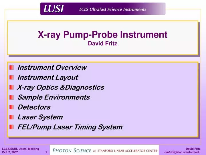
X-ray Pump-Probe Instrument David Fritz. Instrument Overview Instrument Layout X-ray Optics &Diagnostics Sample Environments Detectors Laser System FEL/Pump Laser Timing System. Science Team. The XPP team leaders Kelly Gaffney, Photon Science, SLAC (leader)

E N D
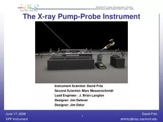
X-ray Pump-Probe Instrument David Fritz • Instrument Overview • Instrument Layout • X-ray Optics &Diagnostics • Sample Environments • Detectors • Laser System • FEL/Pump Laser Timing System
Science Team The XPP team leaders • Kelly Gaffney, Photon Science, SLAC (leader) • Jorgen Larsson, Lund Institute of Technology, Sweden • David Reis, University of Michigan • Thomas Tschentscher, DESY, Germany • Specifications and instrument concept developed with the science team.
XPP Instrument Scope • Versatility is key to the instrument success Instrument will operate in the 6-25 keV photon energy range
FEE Diagnostics Diagnostics Attenuators Primary Slits NEH Hutch 3 Diagnostics Diagnostics Laser Port Diffractometer Diagnostics Instrument Specifications Photon Shutter Monochromator Photon Shutter Focusing Lenses Mirror System Secondary Slits Wide Angle Stage Small Angle Stage Photon Shutter
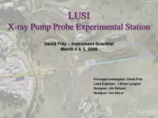
XPP Endstation XPP Instrument Location CXI XCS AMO (LCLS)
Laser System (Fundamental) X-ray Diffractometer & BNL Detector X-ray Optics and Diagnostics Small Angle Scattering Wavelength Conversion Offset Monochromator X-ray Pump-Probe Instrument
X-ray Optics – Offset Monochromator • Double crystal offset monochromator • Narrows x-ray spectrum for resonant scattering experiments • Multiplexes LCLS beam (mono. beam, diagnostic beam)
X-ray Optics - Attenuators • Attenuators • Variable, up to 10 7 reduction at 8.3 keV • Coherence preserving • High damage threshold
X-ray Optics – Slit Systems D. Le Bolloc’h et al., J. Synchrotron Rad., 9, 258-265 (2002). • Slit systems • Variable horizontal and vertical gap from 5 μm – 5 mm • Can withstand full LCLS flux – unfocused • Minimize background scatter from blades
X-ray Optics - Be Focusing Lenses B. Lengeler et al., J. Synchrotron Rad., 6, 1153-1167 (1999). • Beryllium CRL • > 40% throughput • Positioning resolution and repeatability to 1 µm • Z translation to vary spot size
10-2 10-3 10-4 10-5 10-6 X-ray Optics – Harmonic Rejection Mirrors • Harmonic Rejection Mirror System • > 80% throughput • 10 5 : 1 contrast ratio (10 7 : 1 overall)
Kappa Diffractometer α= 50º δ η φ x κ Kinematic Mount μ ν XY Table • Kappa X-ray Diffractometer • Operate in both direct and monochromatic beam • Large reciprocal space access • Gas stream temperature control
Platform Diffractometer δ x trans z trans y trans χ ω Kinematic Mount μ ν XY Table • Platform X-ray Diffractometer • Operate in both direct and monochromatic beam • Accommodates large sample environments (Cryostats, vacuum chambers, etc…)
Emission Spectroscopy XAMPS vertical cut top view δ PSD spectrum analyzers sample analyzers μ beam ν XY Table • X-ray Emission Spectrometer • ~ 50 eV dynamic range • ~ 0.1 eV resolution • Large collection solid angle
Small Angle Scattering • SAXS Capability • 2.5, 5, and 10 m sample-to-detector distance • 10 µrad angular resolution with XAMPS detector (10 m) • Operate in both direct and monochromatic beam
2D Detectors • 2D detector (BNL) • 1024 x 1024 pixels • 90 micron pixel size • High Detector Quantum Efficiency (DQE) • 10 4 dynamic range at 8 keV • 120 Hz Readout Rate
Laser System Ti:Sapphire Oscillator & Power Amplifiers Compressor, OPA, Harmonic Generation, Delay Stage
Laser System • Laser Diagnostics • Temporal and spectral characterization • Grenouille – Real time pulse duration, spectrum • 3rd Order Correlator – Contrast ratio • Energy characterization • Per pulse Joule meter, 120 Hz, 1% accuracy • Spatial characterization • Profile monitor at a “virtual” sample, 5 μm resolution
X-ray Diagnostics • Transmissive Intensity Monitor • > 95 % Transmission • Relative accuracy < 0.1% • Flourescent Screeens • Diodes
Laser/FEL Timing Master Clock RF Distribution Network Accelerating Elements Experimental Pump Laser Electron Gun • Sources of Short Term Jitter • E-beam phase to RF phase jitter • Electron beam energy jitter + dispersive electron optics • End station laser phase to RF Phase • ~ 1 ps limit
Traditional Pump-probe C. W. Siders Delay will be achieved by optical delay and/or RF phase shift Resolution limited by LCLS/laser jitter ~ 1 ps limit
Single Shot Pump-Probe diffracted intensity time (fs) A. M. Lindenberg et al., Science, 308, 392 (2005). Limited to X-ray diffraction Need ‘large’ effects Imaging resolution affects temporal resolution
Laser/FEL Timing • Electro-optic Sampling • Enhanced Temporal Resolution (~ 100 fs) • Limited by our ability to phase lock the lasers to the RF backbone • Limited by Intra-bunch SASE jitter Stabilized Fiber Optic RF Distribution (10 fs) LBNL Electro-optic Sampling Laser Pump-probe Laser Gun Laser Sector 20 LTU NEH
Non-sequential Sampling D. M. Fritz et al., Science, 315, 633 (2007). A. L. Cavalieri et al., Phys. Rev. Lett., 94, 114801 (2005).
Summary • Instrument design emphasizes flexibility • X-ray scattering techniques • WAXS • SAXS • Emission spectroscopy • X-ray optics can tailor FEL parameters for users • Many sample environments are accommodated • Vacuum • Low temperature (cryostat, cryostream) • Samples in solution • Versatile laser system