Download

1 / 35
350 likes | 524 Views
ER Model . Contn. DEVELOPING AN ER DIAGRAM. The process of database design is an iterative rather than a linear or sequential process. The verb iterate means “ to do again or repeatedly.” An iterative process is, thus, one based on repetition of processes and procedures.

E N D
ER Model Contn
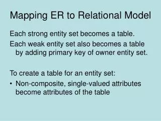
DEVELOPING AN ER DIAGRAM • The process of database design is an iterative rather than a linear or sequential process. • The verb iterate means “to do again or repeatedly.” • An iterative process is, thus, one based on repetition of processes and procedures. • Building an ERD usually involves the following activities: • Create a detailed narrative of the organization’s description of operations. • Identify the business rules based on the description of operations. • Identify the main entities and relationships from the business rules. • Develop the initial ERD. • Identify the attributes and primary keys that adequately describe the entities. • Revise and review the ERD.
During the review process, it is likely that additional objects, attributes, and relationships will be uncovered. • Therefore, the basic ERM will be modified to incorporate the newly discovered ER components. • Subsequently, another round of reviews might yield additional components or clarification of the existing diagram. • The process is repeated until the end users and designers agree that the ERD is a fair representation of the organization’s activities and functions. • During the design process, the database designer does not depend simply on interviews to help define entities, attributes, and relationships. • A surprising amount of information can be gathered by examining the business forms and reports that an organization uses in its daily operations.
To illustrate the use of the iterative process that ultimately yields a workable ERD, let’s start with an initial interview with the Tiny College administrators. The interview process yields the following business rules: • Tiny College (TC) is divided into several schools: a school of business, a school of arts and sciences, a school of education, and a school of applied sciences. Each school is administered by a dean who is a professor. Each professor can be the dean of only one school, and a professor is not required to be the dean of any school.Therefore, a 1:1 relationship exists between PROFESSOR and SCHOOL. Note that the cardinality can beexpressedby writing (1,1) next to the entity PROFESSOR and (0,1) next to the entity SCHOOL.
Each school comprises several departments. For example, the school of business has an accounting department, a management/marketing department, an economics/finance department, and a computer information systems department. Note again the cardinality rules: The smallest number of departments operated by a school is one, and the largest number of departments is indeterminate (N). On the other hand, each department belongs to only a single school; thus, the cardinality is expressed by (1,1). That is, the minimum number of schools that a department belongs to is one, as is the maximum number. Figure 4.26 illustrates these first two business rules.
Note • It is again appropriate to evaluate the reason for maintaining the 1:1 relationship between PROFESSOR and SCHOOL in the PROFESSOR is dean of SCHOOL relationship. • It is worth repeating that the existence of 1:1 relationships often indicates a misidentification of attributes as entities. • In this case, the 1:1 relationship could easily be eliminated by storing the dean’s attributes in the SCHOOL entity. • This solution would also make it easier to answer the queries, “Who is the dean?” and “What are that dean’s credentials?” • The downside of this solution is that it requires the duplication of data that are already stored in the PROFESSOR table, thus setting the stage for anomalies. • However, because each school is run by a single dean, the problem of data duplication is rather minor. • The selection of one approach over another often depends on information requirements, transaction speed, and the database designer’s professional judgment. • In short, do not use 1:1 relationships lightly, and make sure that each 1:1 relationship within the database design is defensible.
Each department may offer courses. For example, the management/marketing department offers courses such as Introduction to Management, Principles of Marketing, and Production Management. The ERD segment for this condition is shown in Figure 4.27. Note that this relationship is based on the way Tiny College operates. If, for example, Tiny College had some departments that were classified as “research only,” those departments would not offer courses; therefore, the COURSE entity would be optional to the DEPARTMENT entity. • The relationship between COURSE and CLASS was illustrated in Figure 4.9. Nevertheless, it is worth repeating that a CLASS is a section of a COURSE. That is, a department may offer several sections (classes) of the same database course. Each of those classes is taught by a professor at a given time in a given place. In short, a 1:M relationship exists between COURSE and CLASS. However, because a course may exist in Tiny College’s course catalog even when it is not offered as a class in a current class schedule, CLASS is optional to COURSE. Therefore, the relationship between COURSE and CLASS looks like Figure 4.28.
Each department should have one or more professors assigned to it. One and only one of those professors chairs the department, and no professor is required to accept the chair position. Therefore, DEPARTMENT is optional to PROFESSOR in the “chairs” relationship. Those relationships are summarized in the ER segment shown in Figure 4.29. Each professor may teach up to four classes; each class is a section of a course. A professor may also be on a research contract and teach no classes at all. The ERD segment in Figure 4.30 depicts those conditions.
A student may enroll in several classes but takes each class only once during any given enrollment period. For example, during the current enrollment period, a student may decide to take five classes—Statistics, Accounting, English, Database, and History—but that student would not be enrolled in the same Statistics class five times during the enrollment period! Each student may enroll in up to six classes, and each class may have up to 35 students, thus creating an M:N relationship between STUDENT and CLASS. Because a CLASS can initially exist (at the start of the enrollment period) even though no students have enrolled in it, STUDENT is optional to CLASS in the M:N relationship. This M:N relationship must be divided into two 1:M relationships through the use of the ENROLL entity, shown in the ERD segment in Figure 4.31. But note that the optional symbol is shown next to ENROLL. If a class exists but has no students enrolled in it, that class doesn’t occur in the ENROLL table. Note also that the ENROLL entity is weak: it is existence-dependent, and its (composite) PK is composed of the PKs of the STUDENT and CLASS entities. You can add the cardinalities (0,6) and (0,35) next to the ENROLL entity to reflect the business rule constraints, as shown in Figure 4.31.
Each department has several (or many) students whose major is offered by that department. However, each student has only a single major and is, therefore, associated with a single department. However, in the Tiny College environment, it is possible—at least for a while—for a student not to declare a major field of study. Such a student would not be associated with a department; therefore, DEPARTMENT is optional to STUDENT. It is worth repeating that the relationships between entities and the entities themselves reflect the organization’s operating environment. That is, the business rules define the ERD components. • Each student has an advisor in his or her department; each advisor counsels several students. An advisor is also a professor, but not all professors advise students. Therefore, STUDENT is optional to PROFESSOR in the “PROFESSOR advises STUDENT” relationship.
As you can see in Figure 4.34, the CLASS entity contains a ROOM_CODE attribute. Given the naming conventions, it is clear that ROOM_CODE is an FK to another entity. Clearly, because a class is taught in a room, it is reasonable to assume that the ROOM_CODE in CLASS is the FK to an entity named ROOM. In turn, each room is located in a building. So the last Tiny College ERD is created by observing that a BUILDING can contain many ROOMs, but each ROOM is found in a single BUILDING. In this ERD segment, it is clear that some buildings do not contain (class) rooms. For example, a storage building might not contain any named rooms at all.
Using the preceding summary, you can identify the following entities: • SCHOOL • COURSE • DEPARTMENT • CLASS • PROFESSOR • STUDENT • BUILDING • ROOM • ENROLL (the associative entity between STUDENT and CLASS)
Once you have discovered the relevant entities, you can define the initial set of relationships among them. • Next, you describe the entity attributes. • Identifying the attributes of the entities helps you to better understand the relationships among entities. • Table 4.4 summarizes the ERM’s components, and names the entities and their relations.
You must also define the connectivity and cardinality for the just-discovered relations based on the business rules. • However, to avoid crowding the diagram, the cardinalities are not shown. • Figure 4.35 shows the Crow’s Foot ERD for Tiny College. • Note that this is an implementation-ready model. • Therefore it shows the ENROLL composite entity. • Figure 4.36 shows the conceptual UML class diagram for Tiny College. Note that this class diagram depicts the M:N relationship between STUDENT and CLASS. • Figure 4.37 shows the implementation-ready UML class diagram for Tiny College (note that the ENROLL composite entity is shown in this class diagram.
DATABASE DESIGN CHALLENGES: CONFLICTING GOALS • Database designers often must make design compromises that are triggered by conflicting goals, such as adherence to design standards (design elegance), processing speed, and information requirements. • Design standards. The database design must conform to design standards. Such standards have guided you in developing logical structures that minimize data redundancies, thereby minimizing the likelihood that destructive data anomalies will occur. You have also learned how standards prescribe avoiding nulls to the greatest extent possible. In fact, you have learned that design standards govern the presentation of all components within the database design. In short, design standards allow you to work with well-defined components and to evaluate the interaction of those components with some precision. Without design standards, it is nearly impossible to formulate a proper design process, to evaluate an existing design, or to trace the likely logical impact of changes in design.
Processing speed. In many organizations, particularly those generating large numbers of transactions, high processing speeds are often a top priority in database design. High processing speed means minimal access time, which may be achieved by minimizing the number and complexity of logically desirable relationships. For example, a “perfect” design might use a 1:1 relationship to avoid nulls, while a higher transaction-speed designmightcombine the two tables to avoid the use of an additional relationship, using dummy entries to avoid the nulls. If the focus is on data-retrieval speed, you might also be forced to include derived attributes in the design. • Information requirements. The quest for timely information might be the focus of database design. Complex information requirements may dictate data transformations, and they may expand the number of entities and attributes within the design. Therefore, the database may have to sacrifice some of its “clean” design structures and/or some of its high transaction speed to ensure maximum information generation.
For example, suppose that a detailed sales report must be generated periodically. • The sales report includes all invoice subtotals, taxes, and totals; even the invoice lines include subtotals. • If the sales report includes hundreds of thousands (or even millions) of invoices, computing the totals, taxes, and subtotals is likely to take some time. • If those computations had been made and the results had been stored as derived attributes in the INVOICE and LINE tables at the time of the transaction, the real-time transaction speed might have declined. • But that loss of speed would only be noticeable if there were many simultaneous transactions. • The cost of a slight loss of transaction speed at the front end and the addition of multiple derived attributes is likely to pay off when the sales reports are generated (not to mention the fact that it will be simpler to generate the queries).
A design that meets all logical requirements and design conventions is an important goal. • However, if this perfect design fails to meet the customer’s transaction speed and/or information requirements, the designer will not have done a proper job from the end user’s point of view. • Compromises are a fact of life in the real world of database design. • Even while focusing on the entities, attributes, relationships, and constraints, the designer should begin thinking about end-user requirements such as performance, security, shared access, and data integrity. • The designer must consider processing requirements and verify that all update, retrieval, and deletion options are available. • Finally, a design is of little value unless the end product is capable of delivering all specified query and reporting requirements.
You are quite likely to discover that even the best design process produces an ERD that requires further changes mandated by operational requirements. • Such changes should not discourage you from using the process. ER modeling is essential in the development of a sound design that is capable of meeting the demands of adjustment and growth. • Using ERDs yields perhaps the richest bonus of all: a thorough understanding of how an organization really functions. • There are occasional design and implementation problems that do not yield “clean” implementation solutions. • To get a sense of the design and implementation choices a database designer faces, let’s revisit the 1:1 recursive relationship “EMPLOYEE is married to EMPLOYEE” first examined in Figure 4.18. Figure 4.38 shows three different ways of implementing such a relationship.
Note that the EMPLOYEE_V1 table in Figure 4.38 is likely to yield data anomalies. • For example, if Anne Jones divorces Anton Shapiro, two records must be updated—by setting the respective EMP_SPOUSE values to null—to properly reflect that change. • If only one record is updated, inconsistent data occur. The problem becomes even worse if several of the divorced employees then marry each other. • In addition, that implementation also produces undesirable nulls for employees who are not married to other employees in the company. • Another approach would be to create a new entity shown as MARRIED_V1 in a 1:M relationship with EMPLOYEE. • This second implementation does eliminate the nulls for employees who are not married to somebody working for the same company. (Such employees would not be entered in the MARRIED_V1 table.) • However, this approach still yields possible duplicate values. For example, the marriage between employees 345 and 347 may still appear twice, once as 345,347 and once as 347,345. (Since each of those permutations is unique the first time it appears, the creation of a unique index will not solve the problem.)
As you can see, the first two implementations yield several problems: • Both solutions use synonyms. The EMPLOYEE_V1 table uses EMP_NUM and EMP_SPOUSE to refer to an employee. The MARRIED_V1 table uses the same synonyms. • Both solutions are likely to produce inconsistent data. For example, it is possible to enter employee 345 as married to employee 347 and to enter employee 348 as married to employee 345. • Both solutions allow data entries to show one employee married to several other employees. For example, it is possible to have data pairs such as 345,347 and 348,347 and 349,347, none of which will violate entity integrity requirements, because they are all unique.
A third approach would be to have two new entities, MARRIAGE and MARPART, in a 1:M relationship. • MARPART contains the EMP_NUM foreign key to EMPLOYEE. (See the relational diagram in Figure 4.38.) • But even this approach has issues. It requires the collection of additional data regarding the employees’ marriage—the marriage date. If the business users do not need this data, then requiring them to collect it would be inappropriate. • To ensure that an employee occurs only once in any given marriage, you would have to create a unique index on the EMP_NUM attribute in the MARPART table. • Another potential problem with this solution is that the database implementation will allow more than two employees to “participate” in the same marriage.
As you can see, a recursive 1:1 relationship yields many different solutions with varying degrees of effectiveness and adherence to basic design principles. • Any of the above solutions would likely involve the creation of program code to help ensure the integrity and consistency of the data. • Your job as a database designer is to use your professional judgment to yield a solution that meets the requirements imposed by business rules, processing requirements, and basic design principles. • Finally, document, document, and document! Put all design activities in writing. Then review what you’ve written. • Documentation not only helps you stay on track during the design process, but also enables you (or those following you) to pick up the design thread when the time comes to modify the design. • Although the need for documentation should be obvious, one of the most vexing problems in database and systems analysis work is that the “put it in writing” rule is often not observed in all of the design and implementation stages. • The development of organizational documentation standards is a very important aspect of ensuring data compatibility and coherence.
Exercise • Use the following business rules to create a Crow’s Foot ERD. Write all appropriate connectivitiesand cardinalities in the ERD. • a. A department employs many employees, but each employee is employed by only one department. • b. Some employees, known as “rovers,” are not assigned to any department. • c. A division operates many departments, but each department is operated by only one division. • d. An employee may be assigned many projects, and a project may have many employees assigned to it. • e. A project must have at least one employee assigned to it. • f. One of the employees manages each department, and each department is managed by only one employee. • g. One of the employees runs each division, and each division is run by only one employee.