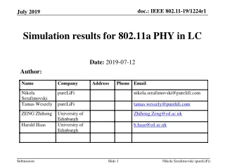
802.11a Presentation
802.11a Presentation. EE206a Spring 2002 Raghu Rao Kevin Chen. 802.11a Presentation Outline. 802.11a General Information/Specifications 802.11a channel specifications OFDM modulation scheme Transmitter Receiver Packet Structure MAC layer Enhancements to 802.11a in the 5-UP protocol

802.11a Presentation
E N D
Presentation Transcript
802.11a Presentation EE206a Spring 2002 Raghu Rao Kevin Chen
802.11a Presentation Outline • 802.11a General Information/Specifications • 802.11a channel specifications • OFDM modulation scheme • Transmitter • Receiver • Packet Structure • MAC layer • Enhancements to 802.11a in the 5-UP protocol • Performance of 802.11a from Atheros • 802.11g and 802.11e • Bibliography
802.11 General Information • 802.11a is a wireless LAN standard operating at 5 GHz carrier frequency in 3 unlicensed bands • 5.15 - 5.25 GHz (4 channels of 20 MHz, 40 mW power constraint) • 5.25 - 5.35 GHz (4 channels of 20 MHz, 200 mW power constraint) • 5.725 - 5.825 GHz (4 channels of 20 MHz, 800 mW power constraint) • OFDM modulation with 52 subcarriers • 48 data subcarriers and 4 pilot subcarriers • BPSK, QPSK, 16-QAM or 64-QAM constellation on each subcarrier • convolutional coding • Throughput supported: 6, 9, 12, 18, 24, 36, 48 and 54 Mbps • Access method primarily based on contention with some polling capabilities as well. • Dedicated central controller based; Access Point (AP)
OFDM Physical layer details • 64 point IFFT/FFT (3.2 us) • Guard Interval of 16 (aka cyclic prefix) • To maintain orthogonality of subcarriers by exploiting periodicity/cyclic nature of FFT • Robust for timing offsets and multipaths • A simple 1 tap FEQ at the receiver • Good for an environment with an rms delay spread (rms) of 125-150ns • Cyclic prefix or GI needs to be slightly more than the max delay spread of the channel. • Orthogonality of subcarriers is lost • Interblock interference • Typically GI is approx 4-8 times rms • This is a tradeoff between QoS and throughput • Subcarrier spacing of ~300 KHz
BlockShaping • Extremely sensitive to carrier freq offsets. Need better than 30ppm accuracy on frequency locking. • A frequency shift of more than half the subcarrier spacing will make it difficult to recover data. (~150 KHz) • Block shaping (symbol wave shaping) for smaller ICI. • Raised cosine window function • Results in much smaller side lobes
802.11a Packet Structure • PLCP preamble – for synchronization (includes training symbols). • Signal field: • Rate – Data rate: 6, 9, 12, 18, 24, 36, 48, 54 Mbps coded with 4 bits (1101…0011). • Reserved – for future use. • Length – # of octets in MPDU that MAC is requesting PHY to transfer (1 - 4095). • Parity – Parity (even) for Rate, Reserved, and Length fields. • Tail – All bits set to zero; allows timely detection of Rate and Length fields. • Data field (Service, PSDU, Tail, Pad Bits) – All bits scrambled. • Service – first 7 bits set to zero, remaining 9 bits reserved for future use. • PSDU – Data bits. • Tail - All bits set to zero. • Pad bits – Used to set packet length; set to zero and scrambled with rest of Data field using generator polynomial S(x) = x7+x4+1.
MAC-PHY Layer Interactions • MAC-PHY instructions: • Receive: • PHY_CCA.ind – Clear channel indication from PHY (Busy/Idle). • PHY_RXSTART.ind – Indication from PHY that receive has begun; includes Length and RSSI parameters. • PHY_DATA.ind – Indication from PHY that data is arriving. • PHY_TXEND.ind – Indication from PHY that transmission has ended. • Transmit: • PHY_TXSTART.req – Instruction to PHY to initiate transmission; includes parameters: Length, DataRate, Service, TXPWR_LEVEL. • PHY_TXSTART.conf – Confirmation from PHY that transmission has begun. • PHY_DATA.req – Request to PHY for data transmission. • PHY_DATA.conf – Transmission confirmation from PHY. • PHY_TXEND.req – “End of Transmission” signal sent to PHY. • PHY_TXEND.conf – “End of Transmission” confirmation from PHY.
802.11a Performance Data from Atheros • Measurement setup by Atheros: • Using Atheros 802.11a PC cards, using Atheros AR5000 chipset with 14dBm power to antenna. • Comparison equipment: 802.11b system with 15dBm to antenna. • Experiment conducted in Atheros’ office building (265 x 115ft) with conference rooms, closed offices, walls, and semi-open cubicles. • Metrics: • Throughput Range Performance – Throughput as a function of distance. • System capacity – Throughput of entire WLAN system comprised of cells (each with an area of coverage).
Throughput Range Performance • Throughput is the actual rate of information, accounting for overheads (PER, MAC efficiency, collisions, etc.) as opposed to Data Link Rate, which is the ideal link rate yielding the highest throughput. • The throughput of 802.11a is 2 to 4.5 times better than 802.11b. (Ex: At 225 ft, 802.11a averages yielded 5.2 Mbps compared to 1.6 Mbps for 802.11b averages.)
Throughput Range Performance • Averaged throughput performance for 1500 byte packets: 802.11a thoughputs always better by 2 to 4.5 times up to 225 ft.
System Capacity • For a common cell radius of 65 ft, 802.11a average cell throughput is 4.5 times that of 802.11b: 22.6 Mbps vs. 5.1 Mbps. • Ex: To match 802.11a throughput, an 802.11b system would need more than 4 access points deployed in the same area. But this is not possible due to CCI (Co-Channel Interference), since 802.11b only utilizes 3 distinct channels compared to 802.11a, which has 8 (lower UNII bands). 8-cell CCI example
System Capacity • For a typical cell radius of 65 ft, an 8-cell 802.11a system provides more than 8 times the average system capacity of an 8-cell 802.11b system.
Enhancements to 802.11a The 5-UP Protocol • 5-UP is a proposed extension to 802.11a that provides data transfer rates up to 54 Mbps and allows other lower-power, lower-speed devices (cordless phones, PDAs, networked appliances) to share the same wireless network.
5-UP Protocol • Scalability: Different nodes use different subsets of OFDM carriers. Lower data rate devices can use fewer subcarriers.
5-UP PHY Layer Constraints • 1. Frequency Control • Problem: Signals need to be frequency-accurate to one another within a few ppm to maintain isolation between carriers. • Solution: Nodes can extract frequency off-set of the Access Point (AP) relative to node’s local frequency reference (crystal). • 2. Timing Control • Problem: All signals must arrive at the Access Point within a guard interval of 800ns. • Solution: • Indoor: Alignment of ±100ns is sufficient and can be timed off received signals from AP. • Outdoor: AP advises nodes to begin transmitting sooner or later.
5-UP PHY Layer Constraints • 3. Power Control • Problem: Power control is ±3 dB for 5-UP. • Solution: • Closed loop: AP tells each node to increase/decrease transmit power. • Open loop: Nodes change their transmit power based on received power level from AP. • 4. Narrowband Fading and Interference Control • Problem: Can wipe out complete signal from transmitter if only one or few carriers are being used. • Solution: • Antenna diversity: Exploit receive antenna diversity (2-antenna system with pure selection diversity can achieve gains of 8-10 dB). • Subcarrier “hopping” over time: Ex: Transmitter switches between subcarrier 1 and subcarrier 13 over separate transmit periods.
5-UP MAC Layer • Timesharing between traditional 802.11a and 5-UP protocols: PCF (Point Coordination Function) beacon is transmitted to indicate start of a 5-UP period, ended by a CF-end (Contention-free) beacon.
802.11g • OFDM at 2.4 GHz (802.11b space) • Capable of 22 Mbps • Needs to be backward compatible • Too many other standards operating in the same band 2.4 GHz ISM (bluetooth, cordless phones, etc.) is a drawback. • Compatible with 802.11e? questionable at this point!
802.11e • QoS and multimedia enhancements. • Proposes a better way to handle time sensitive traffic • time scheduled and polled communication during contention free periods. • Centralized scheduler guarantees collision avoidance • Improvements in the efficiency of polling • Chain a sequence of polls in a single command for efficiency
802.11e contd… • Ability to honor critical QoS contracts such as latency, jitter, etc. • Band management by a higher layer protocol • The ability to switch frequency bands based on channel condition (QoS) for time critical traffic (virtual streams). Channel allocation made by “bandwidth manager” like higher layer protocols.
Bibliography • McFarland, B.; Chesson, G.; Temme, C.; Meng, T. The 5-UP/sup TM/ protocol for unified multiservice wireless networks. IEEE Communications Magazine, vol.39, (no.11), IEEE, Nov. 2001. p.74-80. • www.atheros.com 802.11a Range and System Capacity Paper http://www.atheros.com/AtherosRangeCapacityPaper.pdf • IEEE standard at http://www.ee.ucla.edu/~mbs/802.11/802.11a-1999.pdf • “OFDM Wireless Multimedia Communications”, Richard Van Nee and Ramjee Prasad. Artech House.