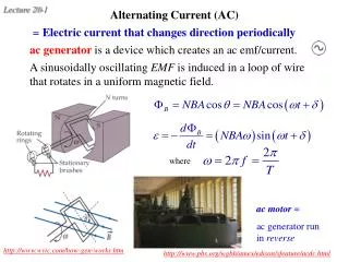

Basic AC Circuits: Analysis and Applications
E N D
Presentation Transcript
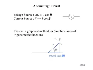
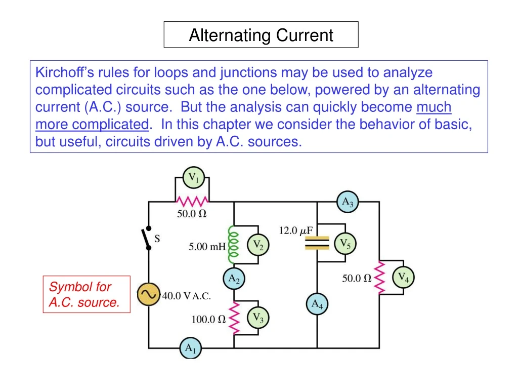
Alternating Current Kirchoff’s rules for loops and junctions may be used to analyze complicated circuits such as the one below, powered by an alternating current (A.C.) source. But the analysis can quickly become much more complicated. In this chapter we consider the behavior of basic, but useful, circuits driven by A.C. sources. Symbol for A.C. source. A.C.
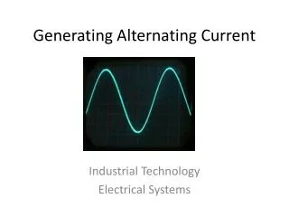
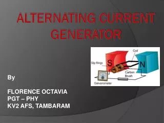
Simple alternating current (A.C.) generator Demo In a basic A.C. generator, a permanent magnet provides a reasonably uniform magnetic field. As the generator loop turns in this field at frequency w(rad/s), the flux through the loop changes sinusoidally with time. This causes the output voltage (induced emf) to also change sinusoidally, 90 degrees out of phase with the flux. We can see why this happens by applying Faraday’s Law of Induction to the flux: Let: Then: Motional emf
Resistor connected to A.C. source Use Kirchoff’s loop equation: So the current in the resistor is: Note that the resistor voltage and current are in phase. (See plot.) Instantaneous power dissipation: To find the average power (root mean square, “RMS”), integrate over one cycle: So that:
Inductor connected to A.C. source Use Kirchoff’s loop equation: Integrate to solve for IL: From either the equations or the graph we see that, for A.C. sources, the current in an inductor lags behind its voltage by 90o
Inductive Reactance, XL Notice that whenever cos(wt) is +1 or -1, the magnitude of the current in the inductor is at the maximum. We can express this as follows: This equation has the same structure as Ohm’s Law, and we can identify the factor in the denominator as setting the ratio between V and I. We call this factor the inductive reactance, and define it as follows: And since RMS voltage and current are one-half their values at maximum, XLcan be used in both equations: • It’s clear from these equations that XL must have units of ohms. • Unlike resistance, inductive reactance changes with frequency! Example
Capacitor connected to A.C. source Kirchoff’s loop equation: Differentiate to find IC: From either the equations or the graph we see that, for A.C. sources, the current in a capacitor leads its voltage by 90o
Capacitive Reactance, XC Again, whenever cos(wt) is +1 or -1, the magnitude of the current in the capacitor is at the maximum. We can express this as follows: This equation has the same structure as Ohm’s Law, and we can identify the factor multiplying V as setting the ratio between V and I. We define the capacitive reactance as the inverse of this factor: And since RMS voltage and current are one-half their values at maximum, XCcan be used in both equations: • As with XL , XC must have units of ohms. • And as before, this capacitive reactance changes with frequency! Example
The Driven RLC Circuit We have already studied the damped oscillations of an RLC circuit which has been energized with an initial charge or current. But now we consider the response of this circuit when it is driven by an AC source, which feeds energy into the circuit. We will see how this reaches an equilibrium, with the power from the source being dissipated by the resistor.
Analyzing the Driven RLC Circuit Since this circuit consists of one loop, the same current, I, passes through every element in the circuit. Once again, we can use Kirchoff’s loop equation for voltages. Using V for the source voltage: Now we insert all the equations from previous pages. With this more complicated circuit the phase of the source will no longer be the same as that for the resistor. So we let the source voltage be displaced by –f. For t = 0: For wt = p/2: Square and add: Define “impedance”, Z: We can think of “impedance”, Z, as “total resistance at a given frequency w.
Frequency dependence of reactances and impedance in RLC Circuit At the frequency where XL= XC, the impedance of the circuit is at a minimum, and Z = R. Since Z is minimum at the point where XL= XC the average current is maximum. The power dissipation is also maximum at this point, meaning that the power delivered to the circuit by the AC source is maximum. At what frequency does this occur? But this is the frequency of an LC circuit when there is no resistor present! At this frequency, the circuit is in resonance, with the driving frequency, w, equal to the natural frequency of the LC oscillator, wo.
Current as a function of w in a driven RLC circuit The plot at right shows current resonance curves for several values of R. The greater the resistance, the lower the maximum current. We can calculate the shapes of these resonance curves as follows:
Resonance curves for a damped, driven harmonic oscillator: mass + spring + damping.
Collapse of Tacoma Narrows bridge in 1940 driven into resonance by wind. Too little damping!
Coils sharing the same magnetic flux, BA These can be used as “transformers”. In air With iron yoke
Raising and Lowering A.C. Voltage: Transformers Faraday’s Law of Induction tells us the relationship between the magnitudes of the voltage at the terminals and the rate of change of magnetic flux through each coil: But the flux through each coil is the same: So the output (secondary) voltage can be raised or lowered compared to the input (primary) voltage, by the ratio of turns. A transformer that raises (lowers) voltage is called a “step-up” (“step-down”) transformer. Transformers lose very little power: As the voltage is increased, the current is lowered by the same factor.
Transformers are not perfect, but they dissipate little power.
Nikola Tesla (Serbian Cyrillic: Никола Тесла; 10 July 1856 – 7 January 1943) was a Serbian-American inventor, mechanical engineer, and electrical engineer. He was an important contributor to the birth of commercial electricity, and is best known for his many revolutionary developments in the field of electromagnetism in the late 19th and early 20th centuries building on the theories of electromagnetic technology discovered by Michael Faraday and used in direct current (DC) applications. Tesla's patents and theoretical work formed the basis of modern alternating current (AC) electric power systems, including the polyphase system of electrical distribution and the AC motor.
Tesla’s A.C. Dynamo (generator) used to generate alternating currrent electricity, which became the technology of choice for electrification across the U.S. (power grids) and ultimately, the whole planet. U.S. Patent 390721
Wardenclyffe Tower facility ~ 1915 Mark Twain in Tesla’s Lab.
A.C. power networks Transmission lines: 155,000-765,000 V Local substation: 7,200 V House: 110/220 V For a given length of power line, P=RI2. If the power line voltage is 550,000 V, the current is reduced by a factor of 5000 compared to that at 110 V, and the power loss is reduced by a factor of 25 million.