Download
1 / 21
210 likes | 229 Views
Improve neutron crystallography data analysis by integrating Bragg peaks efficiently using machine learning for peak shape recognition and background computation.

E N D
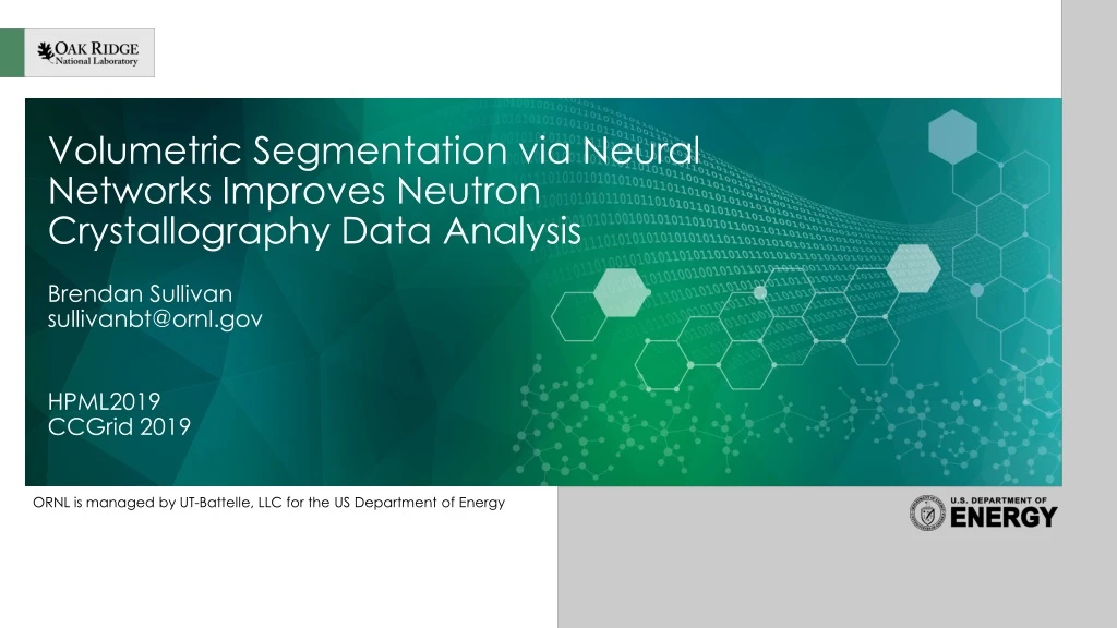
Volumetric Segmentation via Neural Networks Improves Neutron Crystallography Data Analysis Brendan Sullivansullivanbt@ornl.gov HPML2019CCGrid 2019
Oak Ridge National Laboratory hosts the Spallation Neutron Source (SNS) and High Flux Isotope Reactor (HFIR)
Oak Ridge National Laboratory hosts the Spallation Neutron Source (SNS) and High Flux Isotope Reactor (HFIR) • Over 1,000 users in 2018 conducted experiments • Users apply for beamtime through peer-reviewed process • Beamtime is limited, need to make sure experiments are run optimally and data are analyzed thoroughly • Support a large number of techniques, including neutron crystallography The detector array at the MaNDi crystallography Beamline at the SNS
Crystallography is the powerhouse technique for molecular structure determination • The planes of a single act like slits for diffraction • The maxima are known as Bragg Peaks or Bragg Spots • Discovered in early 1900s and used for small molecule structures (e.g. diamond, NaCl) • Protein crystallography is the workhorse for structural biology • Drug-protein interactions • Researching biomimetic technologies
A standard crystallography experiment requires a collection of Bragg peaks to be integrated Find, Index and Predict Peaks Integrate Peaks Fourier Transform to Real Space and Model Building Sample Growth and Data Collection ×100,000
There are several shortcomings for peak-minus-background approaches Adjacent and Inaccurate Peak Weak Peaks Overlapping Peaks Detector Edges Prediction Complicated Peak Shapes Varying Peak Sizes
Overview • Quick overview of Bragg Peak integration using profile fitting • Peak integration as an image segmentation problem • Apply machine learning to integrating Bragg peaks • Generating appropriate training sets • Carrying out the integration • Validating the results • Performance Comparison • Transfer learning • Future applications
We can model a Bragg Peak in reciprocal space as a TOF component times a Bivariate Gaussian • Bragg peaks are 3D intensity profiles in reciprocal space • The time of flight direction is described by an Ikeda-Carpenter function • A Bivariate Gaussian describes the remaining two directions • Using this for peak shape in 3D recovers peak shape • Improves statistics and extends resolution by ~0.3 Å
Determining the background is done by trial and error and is a computationally expensive process • Most accurate method has been to do least squares fit for each background level to known profile • This takes ~1s per peak, need to integrate ~100,000 • End product is the set of voxels that make up a peak • Volumetric segmentation
Training peaks are augmented from measured strong peaks I/max(I) > 0.15 • Can easily fit strong peaks – threshold to get a mask • Need to simulate different orientations, mispredict locations, weak peaks (strong noise)
We use two datasets from two crystals of the same protein as a starting point for looking at transfer learning • Two datasets recorded with same instrument configuration • Crystal for second dataset diffracts more strongly • Both training sets created using same algorithm • Dataset 1 has ~10k peaks, Dataset 2 has ~15k peaks • Mixed training set used 5k from each Size of training peaks for each dataset
A small neural network similar to a U-Net is used to learn peak shapes from training data • Train against ~10k training peaks generated from strong peaks • ADAM optimizer, lr = 0.0005, β1=0.9, β2=0.999 • Includes dropout layers (0.5 dropout rate) and BatchNormalization layers • Total of 103,873 trainable variables and 320 nontrainable • 80% training, 10% validation, 10% test from training set
Using a small network based on a U-Net the network is able to learn peak shapes • For training and prediction, scale data to have zero mean and unit variance • Loss function: 1-Dice Coefficient • Routinely achieve Dice coefficients of 0.82, mean IoUs of 0.69 for training, validation, and testing sets. • For negative control, fit to random peaks. 0.15 Dice Coefficient
Trained network successfully segments peaks over a variety of intensities • Predicts non-training peaks reliably • For weakest peaks, cannot visually determine if prediction is accurate • Integration to get intensity and variance: • Need to quantitatively assess integration for consistency (merging statistics) and accuracy (intensity statistics) • Keep I/σ > 1 for each integration method
Merging statistics measure consistency of integrated intensities Dataset 1 Dataset 2
Ideal crystals have known intensity statistics that we can use to evaluate integration scheme performance • Series of tests based on intensity statistics • Usually diagnose issues with sample • From X-ray we know these are nearly perfect crystals, so we use to assess integration scheme • N(z) tests measure the distribution of intensities • N(|L|) tests variations in local intensity
Intensity Distributions demonstrate that profile fitting integration is more accurate
This work demonstrates transfer learning is possible for peak integration • No major differences between statistics or maps depending which set we train against • First step towards developing a universally applicable integration network • This is needed for new samples that users bring • More recent work shows extends beyond the similar crystals • Especially for more challenging samples
Integration using a neural network is ~100 x faster • Profile fitting takes several hours to integrate • Users need faster feedback to inform how they use beamtime • Using neural networks, we gain a factor of 100 increase in speed • Envision deploying for large scale autoreduction to give near real-time feedback
Future neutron and X-ray sources can benefit from deep learning-based data analysis • New XFELs will produce data at a rate of ~100 GB/s and require near real-time peak integration • Peaks not perfectly modeled yet, may need ML for accuracy and speed • Next generation of neutron sources will have much higher fluxes • Electron diffraction uses electrons instead of neutrons – remains difficult to model European Spallation Source (Under Construction) Electron Diffraction Pump-Probe Crystallography at LCLS (from LCLS website)
Acknowledgements • ORNL: Rick Archibald, Vickie Lynch, Leighton Coates, Patricia S. Langan, VenuVandavassi, Paul Langan • Samples used for testing grown at the Center for Structural and Molecular Biology, ORNL by Holger Dobbek and Martin Bommer (Humboldt-Universitatzu Berlin), Robert McFeeters (University of Alabama, Huntsville), Martin Egli and Joel Harp (Vanderbilt University) • Funding: NIH R01-GM071939