Download
1 / 28
280 likes | 461 Views
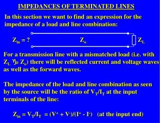
IMPEDANCES OF TERMINATED LINES. In this section we want to find an expression for the impedance of a load and line combination:. Z in = ? Z o Z L.

E N D
IMPEDANCES OF TERMINATED LINES In this section we want to find an expression for the impedance of a load and line combination: Zin = ? Zo ZL For a transmission line with a mismatched load (i.e. with ZLg Zo) there will be reflected current and voltage waves as well as the forward waves. The impedance of the load and line combination as seen by the source will be the ratio of VT/IT at the input terminals of the line: Zin = VT/IT = (V+ + V-)/(I+ - I-) (at the input end)
I I+ I- Zin = V/I V V+ Zo V- ZL x = -l x = 0 Take the load to be at x = 0 and the input to be at x = -l (this allows the forward wave to propagate in the +ve x direction). VT = V+ + V- = Vi e-gxejwt + Vr e+gxejwt => VT = Vi e-gxejwt + rVi e+gxejwt (since Vr / Vi = r) Hence the voltage at the input end of the line (i.e. at x = -l ) is: V-l = Viejwt (egl+ re-gl)
V-l = Viejwt(egl + re-gl ) Similarly, the total current at any point on the line will be: IT = I+ - I- = Ii e-gx ejwt - Ire+gxejwt => IT = (Vi/Zo) e-gxejwt - r(Vi/Zo) e+gx ejwt (since Vr / Vi = r and Ii = Vi/Zo) Hence the current at the input end of the line (i.e. at x = -l ) is: I-l = (Vi/Zo) ejwt(egl- re-gl )
Because of the relations between the hyperbolic functions [sinh(x), cosh(x) and tanh(x)] and the exponential function we can write the expression for Zin in two other equivalent forms. Using these relationships and the equation relating the voltage reflection coefficient to ZL and Zo
…we can express Zin as: or: Original expression: All three expressions are equivalent – which one you use depends on whether you know ZL or ρ.
In the case of a lossless line a = 0, so g = a + jb = jb and is purely imaginary, so the hyperbolic functions reduce to trigonometric functions: Zin becomes: or: Original expression:
Part 2 - Characteristic Impedance and Reflections Lecture Topics 4. Current and voltage on a transmission line: Characteristic impedance, ZO Characteristic impedance of lossless lines Characteristic impedance of general lines Infinitely long transmission lines Reflections on transmission lines 5. Transmission line with change of ZO: voltage reflection coefficient Voltage reflection coefficient at an arbitrary distance l from the load ZL 6. Impedances of terminated lines Voltage Standing Wave Ratio (VSWR) Voltage Standing Wave measurement
Phasor representation of voltage waves The total voltage is given by: V = Vi ejwte-gx + Vr ejwte+gx = Vi ejwte-gx + rViejwte+gx ( since Vr = rVi) For a lossless line g = jb and for a point at a distance l from the load, x = -l . Also, r = |r|ejf, hence: V = Viejwtejbl +|r|Vi ejwtej(f-bl) forward wave backward wave We can represent each of these voltage waves as a phasor.
x = -l x = 0 f-bl l increases as we move down the line away from the load V = Viejwtejbl + |r|Vi ejwtej(f-bl) anticlockwise Vi V clockwise bl |r|Vi Phase difference between the incident and reflected waves is f - 2bl
x = -l x = 0 l increases as we move down the line away from the load V = Viejwtejbl + |r|Vi ejwtej(f-bl) Vi |r|Vi Maximum value of V will occur when the two phasor voltages are coincident: Vmax =Vi + |r|Vi Minimum value of V will occur when they are pointing in opposite directions: Vmin = Vi- |r|Vi
For voltage maxima, V+ and V- are in phase => f - 2bl = 0 (or multiple of 2p) For voltage minima, V+ and V- are 180o out of phase => f - 2bl = p (or odd multiple of p)
VOLTAGE STANDING WAVE RATIO (VSWR) The total voltage at any point on a transmission line can be expressed as: VT = V = Viejwte-gx +Vrejwte+gx V+ V- The incident and reflected voltage waves will combine to produce a standing wave pattern, i.e. a spatial variation of the AMPLITUDE of the TOTAL VOLTAGE. q The maximum voltage will occur at points where V+ and V- are always in phase: Vmax =Vi + |r|Vi q The minimum voltage will occur at points where V+ and V- are always in antiphase: Vmin =Vi - |r|Vi
Voltage amplitude |V| l/4 Vmax Vmin x x = 0 Zo ZL The Voltage Standing Wave Ratio (VSWR) is defined as: VSWR = Vmax / Vmin Like ρ, the VSWR is a measure of the mismatch between ZL and Zo.
Vmax = Vi + |r| Vi = Vi(1+|r|) Vmin = Vi - |r| Vi = Vi(1–|r|) (since Vr = rVi ) => VSWR =Vmax / Vmin = For r = 0 (i.e. ZL = Zo) VSWR = 1 For r = +1 or -1 (i.e. open or short circuit) VSWR = ∞ So all values of the VSWR lie between 1 and ∞
Example 6.1 - Voltage Standing Wave Ratio (VSWR) Find the VSWR for ZL = 100 +j200 W on a 100 W line.
For voltage maxima, V+ and V- are in phase => f - 2bl = 0 (or multiple of 2p) For voltage minima, V+ and V- are 180o out of phase => f - 2bl = p (or odd multiple of p) Consider a neighbouring maximum and minimum at positions lmax and lmin: f - 2blmax = 0 (1) f - 2blmin = p (2) 2blmax- 2blmin= p (2)-(1) lmax Vmax Vmin lmin x
Hence the distance between neighbouring maxima and minima is lmax - lmin = p/2b But b = 2p/l, hence the distance between a voltage maximum and the adjacent voltage minimum is l/4 l/4 lmax Vmax Vmin lmin x N.B. l is the wavelength of the travelling waves that are giving rise to the standing wave pattern – it is NOT the wavelength of the standing wave.
Consider a transmission line terminated in a short circuit: VT = V+ + V- = 0 at the short circuit so V+ = -V-, the waves are always 180o out of phase at the end of the line, which must be a VT minimum . V+ V+ maximum minimum l/4 V- V- x = -l/4 x = 0 Moving back down the line by l/4: V+ is retarded by 90o (1/4 cycle) V- is advanced by 90o V+ and V- are now in phase, giving a maximum for VT.
VT = V+ + V- and IT = I+ - I- = (V+- V-)/Zo Since I+ = V+/Zo and I- = V-/Zo the voltage and current amplitudes at the voltage maxima and minima are: At Voltage Maxima: Vmax = Vi (1 + |r|) Imin = (Vi/Zo)(1 - |r|) At Voltage Minima: Vmin = Vi (1 - |r|) Imax = (Vi/Zo)(1 + |r|) Hence: current maxima correspond with voltage minima and current minima correspond with voltage maxima
Voltage amplitude |V| l/4 Vmax Vmin Current amplitude | I | x x = 0 l/4 Imax Imin Impedance magnitude |Z| |Z|=|V| / | I | x x = 0 l/4 Zmax Zmin x x = 0
VOLTAGE STANDING WAVE MEASUREMENT The voltage standing wave pattern on a transmission line can be measured using a "slotted line": V voltage probe ZL V E l/4 lmax Vmax Vmin lmin x x = 0 The probe enables the voltage (strictly the E field) to be measured at any point along the slot cut in the outer skin of the line. If the slot is narrow it will not affect the properties of the line or cause reflections.
From measurement of Vmax / Vmin we can obtain the magnitude of r: VSWR =Vmax / Vmin = => |r| = VSWR - 1 VSWR + 1 f, the phase of r , can be found from the positions of the voltage maxima and minima, lmax and lmin. At the first voltage maximum: f - 2blmax = 0 => f = 2blmax = 2(2p/l) lmax radians or f = 2blmax = 2(360/l) lmax degrees
The wavelength l can be determined since the distance between a neighbouring maximum and minimum is l/4: |lmax - lmin| = l/4 Knowing r, the load impedance ZL can be found:
An unknown load, ZL, attached to a 50 Ω air-spaced, lossless slotted line gives a VSWR of 2. The 1st voltage standing wave maximum is 0.7m from the load. The 1st voltage standing wave minimum is 0.3m from the load. Find ZL and the frequency at which the measurement was made. Example 6.2 - Determining an unknown load from slotted line measurements.
SUMMARY q The voltage amplitude is a maximum, Vmax, at points where the incident and reflected voltage waves are always in phase. q The voltage amplitude is a minimum, Vmin, at points where the incident and reflected voltage waves are always 180o out of phase. q The Voltage Standing Wave Ratio (VSWR) is defined as: VSWR = Vmax / Vmin = VSWR, like r, is a measure of the mismatch between ZL and Zo .
q The distance between a neighbouring peak and trough in a voltage standing wave pattern is l/4. q |I| is a maximum when |V| is a minimum |I| is a minimum when |V| is a maximum q |Z| is a maximum when |V| is a maximum |Z| is a minimum when |V| is a minimum
q The voltage standing wave pattern can be measured using a SLOTTED LINE. q Measurement of Vmax and Vmin yields VSWR and |r|. q Measurement of lmax and lmin yields l and f. q VSWR measurements yield r and hence ZL.