Download
1 / 149
1.49k likes | 1.69k Views
Learn about the data link layer functions, including error control, framing, flow control, and addressing. Explore different framing techniques, such as fixed-size and variable-size framing. Understand character-oriented and bit-oriented framing in data communication.

E N D
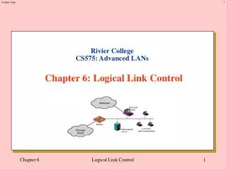
Unit-II Logical Link Control The data link layer transforms the physical layer, a raw transmission facility, to a reliable link. It makes the physical layer appear error-free to the upper layer (network layer).
Data link layer Network Layer Data Link Layer Logical Link Control Sublayer Medium Access Sublayer Physical Layer
IEEE 802 Standard LLC Sublayer IEEE 802.2 Data Link Layer MAC Sublayer Ethernet IEEE 802.5 Token Ring FDDI IEEE 802.4 Token bus IEEE 802.3 (CSMA/CD) Physical Layer Physical Layer LAN Specification OSI Layers
802 Layers functions • Physical • Encoding/decoding • Bit transmission/reception • Transmission medium and topology • Logical Link Control • Interface to higher levels • Flow and error control • Medium Access Control • Data assembly and dismantle into frames • Govern access to LAN transmission medium
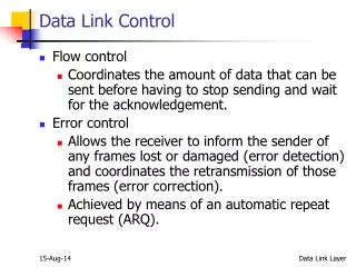
Objective: Achieving reliable communication between two adjacent machines. Design Issues: Framing: Data are sent in blocks called frames, the beginning and end of each frame must be recognized by the receiver. • Error control: Bit errors introduced by the transmission system should be detected and/or corrected.Error control in the data link layer is based on automatic repeat request, which is the retransmission of data.
Flow control: The sending station must not send frames at a rate faster than the receiving station can absorb them. • Flow control refers to a set of procedures used to restrict the amount of data that the sender can send before waiting for acknowledgment. • Addressing: On a multipoint line, such as a LAN, the identity of the two stations involved in a transmission must be specified. • Transmit control information and data on the same line.
Services: • Services provided to the network layer. • 1] Unacknowledged connectionless Service • 2] Acknowledged connectionless Service • 3] Acknowledged connection-oriented • Service
FRAMING The data link layer needs to pack bits into frames, so that each frame is distinguishable from another. Our postal system practices a type of framing. The simple act of inserting a letter into an envelope separates one piece of information from another; the envelope serves as the delimiter.
Framing in the data link layer separates a message from one source to a destination, or from other messages to other destinations, by adding a sender address and a destination address. Fixed-Size Framing: In fixed-size framing, there is no need for defining the boundaries of the frames. Variable-Size Framing: In variable-size framing, we need a way to define the end of the frame and the beginning of the next.
Two approaches were used for this purpose: 1] A character-oriented approach(Protocol). 2] A bit-oriented approach(Protocol).
Data to be carried are 8-bit characters from a • coding system such as ASCII . • The header-the source and destination • addresses and other control information, • The trailer-error detection or error correction • redundant bits • An 8-bit (1-byte) flag is added. • The flag, composed of protocol-dependent • special characters, signals the start or end of a • frame.
Character-oriented framing was popular when only text was exchanged by the data link layers. The flag could be selected to be any character not used for text communication. We send other types of information such as graphs, audio, and video. Any pattern used for the flag could also be part of the information.
A byte-stuffing strategy was added to character-oriented framing. In byte stuffing (or character stuffing), a special byte is added to the data section of the frame This byte is usually called the escape character (ESC). Whenever the receiver encounters the ESC character, it removes it from the data section and treats the next character as data, not a delimiting flag.
Byte stuffing is the process of adding 1 extra byte whenever there is a flag or escape character in the text.
In a bit-oriented protocol, the data section of a frame is a sequence of bits to be interpreted by the upper layer as text, graphic, audio, video, and so on. However, in addition to headers (and possible trailers), we still need a delimiter to separate one frame from the other. Most protocols use a special 8-bit pattern flag 01111110 as the delimiter to define the beginning and the end of the frame.
This flag can create the same type of problem we saw in the byte-oriented protocols. That is, if the flag pattern appears in the data, we need to somehow inform the receiver that this is not the end of the frame. We do this by stuffing 1 single bit (instead of 1 byte) to prevent the pattern from looking like a flag. The strategy is called bit stuffing. In bit stuffing, if a 0 and five consecutive 1 bits are encountered, an extra 0 is added. This extra stuffed bit is eventually removed from the data by the receiver. Note that the extra bit is added after one 0 followed by five 1s regardless of the value of the next bit.
PROTOCOLS The data link layer can combine framing, flow control, and error control to achieve the delivery of data from one node to another. The protocols are normally implemented in software by using one of the common programming languages.
NOISELESS CHANNELS Let us first assume we have an ideal channel in which no frames are lost, duplicated, or corrupted. We introduce two protocols for this type of channel. 1] Simplest Protocol: It does not use flow control. 2] Stop and wait protocol: that does.
1] Simplest Protocol • That has no flow or error control. • Unidirectional protocol. • The receiver can immediately handle any • frame it receives with a processing time. • The receiver can never be overwhelmed • with incoming frames
The design of the simplest protocol with no flow or error control
2] Stop and wait Protocol If data frames arrive at the receiver site faster than they can be processed, the frames must be stored until their use. Normally, the receiver does not have enough storage space, especially if it is receiving data from many sources. This may result in either the discarding of frames. To prevent the receiver from becoming overwhelmed with frames, we somehow need to tell the sender to slow down. There must be feedback from the receiver to the sender.
NOISY CHANNELS The Stop-and-Wait Protocol gives us an idea of how to add flow control, noiseless channels are nonexistent. There are three protocols that are use error control. 1]Stop-and-Wait Automatic Repeat Request(ARQ)2]Go-Back-N Automatic Repeat Request3]Selective Repeat Automatic Repeat Request
1]Stop-and-Wait Automatic Repeat Request(ARQ) : • Adds a simple error control mechanism to • the Stop-and-Wait Protocol. • To detect and correct corrupted frames, • we need to add redundancy bits to our • data frame. • Lost frames are more difficult to handle • than corrupted ones. • No way to identify a frame. • The solution is to number the frames.
The corrupted and lost frames need to • be resent in this protocol. • The sender keeps a copy of the sent • frame. At the same time, it starts a timer. • If the timer expires and there is no ACK for • the sent frame, the frame is resent, the • copy is held, and the timer is restarted. • An ACK frame can also be corrupted and • lost, it too needs redundancy bits and a • sequence number. • The ACK frame for this protocol has a • sequence number field.
Sequence Numbers • The protocol specifies that frames need to • be numbered. • A field is added to the data frame to hold • the sequence number of that frame. • One important consideration is the range • of the sequence numbers. • For the smallest range that provides • unambiguous communication. • For example, if we decide that the field is • m bits long, the sequence numbers start • from 0, go to 2m - 1, and then are repeated.
Acknowledgment Numbers • The sequence numbers must be suitable for both • data frames and ACK frames. • The acknowledgment numbers always announce • the sequence number of the next frame expected • by the receiver. • For example, if frame 0 has arrived safe and sound, • the receiver sends an ACK frame with • acknowledgment 1 (meaning frame 1 is expected • next). • If frame 1 has arrived safe and sound, the • receiver sends an ACK frame with acknowledgment • 0 (meaning frame 0 is expected).
Sender-site algorithm for Stop-and-Wait ARQ (continued)
(continued) Sender-site algorithm for Stop-and-Wait ARQ
Receiver-site algorithm for Stop-and-Wait ARQ Protocol
2] Go-Back-N Automatic Repeat Request : To improve the efficiency of transmission (filling the pipe), multiple frames must be in transition while waiting for acknowledgment. In other words, we need to let more than one frame be outstanding to keep the channel busy while the sender is waiting for acknowledgment.
In this protocol we can send several frames before receiving acknowledgments; we keep a copy of these frames until the acknowledgments arrive. We let the size be fixed and set to the maximum value.
Sequence Numbers Frames from a sending station are numbered sequentially. However, because we need to include the sequence number of eachframe in the header, we need to set a limit. If the header of the frame allows m bits for the sequence number, the sequence numbers range from 0 to 2m - 1. For example, if m is 4, the only sequence numbers are 0 through 15. we can repeat the sequence. 0, 1,2,3,4,5,6, 7,8,9, 10, 11, 12, 13, 14, 15,0, 1,2,3,4,5,6,7,8,9,10, 11, ...
Sliding Window • The problem of “Stop and Wait” is not be able to send multiple packets. • Sliding Window Protocol allows multiple frames to • be in transit. • Receiver has buffer of W (called window size) frames • Transmitter can send up to W frames without ACK • Each frame is numbered. • Sequence number bounded by size of the sequence number field (m bits) • thus frames are numbered modulo 2m(0 … 2m-1) • ACK includes number of next frame expected.