Download
1 / 33
600 likes | 1.46k Views
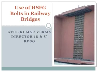
Use of HSFG Bolts in Railway Bridges. Atul Kumar Verma Director (b & s) RDSO. HSFG Bolts – for field connections?. We cannot go for field welds due to quality concerns Rivets is currently the only option for field connection of steel sections

E N D
Use of HSFG Bolts in Railway Bridges Atul Kumar Verma Director (b & s) RDSO
HSFG Bolts – for field connections? • We cannot go for field welds due to quality concerns • Rivets is currently the only option for field connection of steel sections • Riveting is a dying art - Few skilled persons available who can do riveting • Riveting gangs not available especially for small quantum of work • Quality of rivets done at difficult locations not so good • No option but to go in for some alternative like HSFG bolts
HSFG Bolts – Advantages Bolts can be installed much quickly as compared to rivets. Bolt installation does not require much skilled staff as compared to riveting/welding. HSFG bolts have much better fatigue performance as compared with the rivets. Bolts are maintenance free and do not get loose under vibrations.
HSFG Bolts – Concerns There is a concern that bolts can be opened for stealing steel members and for mischief. Proper tightening of bolts is pre-requisite for its performance. Performance of bolts depends on the coefficient of friction between steel surfaces, which depends on the condition of surface at the time of tightening
HSFG Bolts - Introduction • High Strength Friction Grip Bolts • High strength bolts • Having axial force that holds the plies (members) together • BS-111 issued in June 2012 • Revision 6 issued in May 2019.
Correction Slips for HSFG Bolts • A & C Slip no 19 to IRS Steel Bridge Code issued in Jan. 2014 • Covers design issues. • A & C Slip no 27 to IR Bridge Manual issued in Jan. 2014. • Covers maintenance issues. • A & C Slip no 6 to IRS B1 issued. However in May 2019 A&C no. 11 replacing A&C no. 6 issued to cater for supply of HSFG bolting assemblies as per EN 14399 series code. • Covers fabrication and other field issues.
HSFG Bolts – Action Bolts are tightened to stress level beyond yield point Pre-defined load induced in the shank of the bolt The plates/members are pressed together Friction developed at the interface of members resists the external forces
Action of Rivets/ Ordinary Bolts Bearing Action Shearing Action
Action of HSFG Bolts Coefficient of friction decides the load before the surfaces slip
Preloaded HSFG bolting assemblies are very sensitive to differences in manufacture and lubrication. • CompleteHSFG bolting assembly including Direct Tension Indicator (DTI) washer, shall be supplied by single manufacturer who shall be responsible for the function of the assembly. • For the same reason it is important that hot dip galvanizing or other surface coatings of the assembly shall be under the control of single manufacturer. • DTIwashersaretobesoldaspartofacompleteassemblyonly. The systems of bolt/nut/washer assemblies are described in Table below. • Use of DTI washer shall be mandatory in HSFG boltingassemblies.
HSFG Bolts – Identification • Property Class: x.y • x: Tensile strength • y: Ratio of lower yield strength to normal tensile strength • E.g. class 8.8, 10.9 • 8.8 means tensile strength of 800 N/mm2 and lower yield strength 80% of the same i.e. 640 N/mm2 • Identification in field: Along with manufacturer initials, following shall be embossed or indented on head • Class 8.8: HR8.8 • Class 10.9: HR10.9
HSFG Nuts – Identification • Property Class: x • x: Tensile strength • E.g. class 8 and 10, suitable for bolt class 8.8 and 10.9 • Identification in field: Along with manufacturer initials, following shall be embossed or indented on top or bottom • Class 8: HR8 • Class 10: HR10
HSFG Washers Washers used under heads of preloaded bolts shall be chamfered according to EN 14399-6 and positioned with the chamfer towards the bolt head. Washers according to the EN 14399-5 shall only be used under nuts. Up to three washers with a maximum combined thickness of 12 mm may be used in order to adjust the grip length of bolt assemblies. These shall not be thinner than 4 mm. Taper washers shall be used if the surface of the constituent product is at an angle to a plane perpendicular to the bolt axis of more than: (a) 1/20 (3⁰) for bolts with d≤ 20 mm (b) 1/30 (2⁰) for bolts with d> 20 mm. Dimensions and steel grades for taper washers shall be specified
Direct Tension Indicator Compressible washer-type Direct Tension Indicators (DTI) as per EN 14399-9 (known formerly as load indicating washers) used in conjunction with bolt and nut face washers are a load indicating device which are placed under the bolt head or under the nut. The direct tension indicators have protrusions on one face which compress under load and thus may be used to indicate the magnitude of the preload in theassembly.
Action of DTI washer Visual indicator of bolt being properly tightened
How to provide HSFG Bolts Hole: Dia of holes for HSFG bolts shall be 2 mm more than nominal dia of bolt i.e. 22 mm for M20 bolt. Oversize holes: Max 1.25d or d+4 mm. Length of bolt: Shall include grip, all washers and extra constant for nut and projection. Maximum length 10 times dia of bolt
Sequence of tightening bolts Bring holes in alignment using ordinary bolts and drifts Insert bolts and tighten slightly by hand wrenches Starting from more stiff (i.e. central part) to less stiff (i.e. edge part), tighten all bolts to first stage. Check if gap between members has been closed and members are in close contact Re-tighten all bolts, to second stage.
Procedure for tightening of bolts • Using DTI Washer • Performance test of DTI washer shall be done before the same is procured. • First Stage Tightening: Using manual wrench, all bolts shall be tightened to ‘snug tight’ level. • Check if plies are in close contact • Second Stage Tightening: Using Torque wrench, all bolts shall be tightened till DTI indicates full tension in bolt.
Precautions in use of HSFG Bolts Surface preparation is most important and it must be ensured that the metallised surface shall not be painted. Bolts once tightened to second stage go in plastic stage. These cannot be reused in same or other holes. Calibration of DTI washers or torque wrench is very important and adequate care shall be taken for the same .
Anti-theft/anti-sabotage measures Do not use tack welding to destroy bolt thread in any circumstance. Use of proven bonding agent to seize or lock the bolt in position may be applied to the threads projecting beyond the nut. Experimentally, RDSO has found that HSFG bolts upto 20 mm diameter can be opened. Larger bolt diameters require considerable force to open and cannot be opened by stealth.
Status of HSFG Bolts on Indian Railways All spans of Railway Bridges for 25 t loading has been designed with HSFG Bolts and drawing issued. Drawing with rivets have been withdrawn for 25 t loading. It is mandatory to use HSFG bolting assemblies in place of rivets. Drawings of composite girder ROB is also using HSFG bolts for field connection.
Design of joints with HSFG Bolts Choose surface preparation method. IRS SBC specifies two type of preparations and gives the slip factor for these. Metallising as per IRBM (150 μm) without any overcoating shall normally be chosen.
Design of joints with HSFG Bolts Next step is to choose the dia of bolts and the bolt class. 8.8 bolts have lower strength but more reserve strength than 10.9 class bolt. M16, M20, M24, M30 and M36 are given in Is:4000. M18, M22 and M27 are given in IS:1367, referred to as ‘Non Preferred’ sizes. Holes for HSFG bolts are 1.5 mm more than nominal bolt diameter for size upto 25 mm and 2 mm thereafter. Gross area in compression and net area in tension shall be taken as in rivets/ other bolts. Rules for spacing of holes shall be same as for rivets.
Design of joints with HSFG Bolts • For joints subject to pure shear, shear force on a bolt shall not exceed: • Minimum Bolt tension shall be as per Table 3 of IS: 4000. • Factor of safety shall be 1.4. • If wind load is considered, the Factor of safety can be reduced to 1.2 provided the joint is adequate when: • (i) wind forces are not considered, and • (ii) wind load is not the primary loading for the purpose of design
Design of joints with HSFG Bolts Design of joints subject to shear as well as tension:The following equation shall be satisfied: The value of factor F shall be taken as 2.0 if external force is repetitive and 1.7 if non repetitive. Design of joints subject to pure tension:Applied tension in the bolts shall be limited to the values given in table 2 of IS 4000. (Which are equal to 0.6 times the minimum bolt tension specified in table 3 of IS 4000). In case the bolts are subject to tension in fatigue conditions, the minimum tensile force in the bolt shall not exceed 50% of the minimum bolt tension values specified in table 3 of IS 4000.
Design of joints with HSFG Bolts Check on Adequacy of Members connected: The bearing force transmitted between any bolt and any ply shall not exceed 1.2 fy* d * t where fy is yield stress of the ply, d is nominal dia of HSFG bolt and t is the thickness of ply. The component of force acting on the edge of a bolt in the direction of the minimum distance toward the edge of a ply shall not exceed e * fy* t/ 1.4 (where e is edge distance of bolt plus half the bolt diameter, in mm).