Download
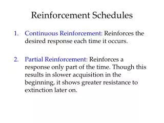
1 / 27
270 likes | 357 Views
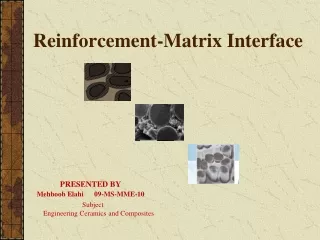
Reinforcement-Matrix Interface. PRESENTED BY Mehboob Elahi 09-MS-MME-10. Subject Engineering Ceramics and Composites. Outlines of Presentation. Introduction Why Interfaces are Important Interface and coatings Wettability Interfacial bonding

E N D
Reinforcement-Matrix Interface PRESENTED BY Mehboob Elahi 09-MS-MME-10 Subject Engineering Ceramics and Composites
Outlines of Presentation Introduction Why Interfaces are Important Interface and coatings Wettability Interfacial bonding Particle –Matrix Compatibility Methods for Bond strength Measurement Interfacial strength Interfaces in PMC,MMC and CMC Interface Failure Importance of adhesion
Introduction Reinforcement
Interface Interface • It is the boundary demarcating the distinct phase of reinforcement and matrix • Zoneacross which matrix and reinforcing phases interact(chemical, physical, mechanical) • For the composite to operate effectively, the phases must bond where they join at the interface (a) direct bonding between primary and secondary phases • Interphase • In some cases, a third ingredient must be added to achieve bonding of primary and secondary phases • Called an interphase, this third ingredient can be thought of as an adhesive /coatings (b) addition of a third ingredient to bond the primary phases and form an interphase
Why are Reinforcement matrix interfaces important? • Ef & Em quite differentSuch large differences are shared through the interface.Stresses acting on the matrix are transmitted to the fiber across the interface. • The interfacial bond can influence • Composite strength • Modes of failure • Young’s modulus • Interlaminar shear strength • Compressive strength • Environmental resistance • Structural stability at elevate temperatures • Fracture and fatigue behavior
Interface and Coatings Interface • To transfer the stress from matrix to reinforcement • The reinforcement must be strongly bonded to the matrix if high stiffness and strength are desired in the composite materials • The interface between fibre and matrix is crucial to the performance of the composite - in particular fracture toughness; corrosion; moisture resistance • Coating • Sometimes surface treatment is carried out to achieve the required bonding to the matrix • Sizing – protect reinforcing material from mechanical damage • Finishes – Enhance bonding of reinforcement to matrix (Polyvinyle acetate or organosilane coupling agent)
Wettability • Is defined the extent where a liquid will spread over a solid surface • During the manufacturing process, the matrix is often in the condition where it is capable of flowing or its behavior is like a liquid • Good wettability means that the liquid (matrix) will flow over the reinforcement, covering every ‘bump’ and ‘dip’ of the rough surface of reinforcement and displacing all air. • Wetting will only occur if the viscosity of the matrix is not too high. • Interfacial bonding exists due to the adhesion between the reinforcement and the matrix (wetting is good) Drops of water on a hydrophobic surface Good or poor wettability?
Let us consider a thin film of liquid (matrix) spreading over a solid (reinforcement) surface • All surfaces have an associated energy and the free energy per unit area of the solid-gas, liquid-gas and solid-liquid are γSG, γLG dan γSL, respectively. • γSG = γLG cos θ + γSL • θ is called the contact angle. May be used as a measure of the degree of the wettability Drops of water on a textile surfacebefore and after addition of wetting agent • cos θ = (γSG – γSL)/ γLG • If θ = 180º, the drop is spherical, no wetting takes place • θ = 0, perfect wetting • 0º<θ<180º, the degree of wetting increases as θ decreases. • Often it is considered that the liquid does not wet the solid if θ>90º • These three quantities determine whether the liquid spreads over the solid, or not; whether it "wets" it. • This is judged by the contact angle, .
Criteria for Better Wetting: • Surface must be free of foreign particles. This removes weak boundary layer or contaminants (H2O, organic vapor, nitrates, ketones, alcohols, amines) • A large interfacial area of intimate contact • Thermodynamically, a high surface-energy surface is the most conductive to good wetting, particularly if adhesive contains polar functional group. • Surface energy of the adherent (reinforcement) should be greater than the adhesive surface energy (matrix). • Creation or addition of chemical group • Variation in surface topography (mechanical interlocking) Improper wetting may cause voids at the interface that may lead to cracking.
Interfacial bonding • Once the matrix has wet the reinforcement, bonding will occur • For a given system, more than one bonding mechanism may exist at the same time • The bondings may change during various production stages or during services Types of interfacial bonding at interface • Mechanical bonding • Electrostatic bonding • Chemical bonding • Reaction or interdiffusion bonding Mechanical bonding • Mechanical interlocking or keying of two interfaces • can leads to reasonable bond • The rougher the interface, the interlocking is • Greater, hence the mechanical bonding is effective • Mechanical bonding is effective when the force is applied parallel to the interface • If the interface is being pulled apart by tensile forces, the strength is likely to be low unless there is a high density of features (designated A)
Electrostatic Bonding • Occur when one surface is positively charged and the other is negatively charge • (refer to the figure) • Interactions are short range and only effective over small distances of the order of atomic dimensions • Surface contamination and entrapped gases will • decrease the effectiveness of this bonding Chemical bonding • The bond formed between chemical groups on the reinforcement surfaces (marked X) and compatiblegroups(marked R) in the matrix • Strength of chemical bonding depends on the number of bonds per unit area and the type of bond • Chemical bonding normally exist due to the application of coupling agents • For example, silanes are commonly employed for coupling the oxide group groups on a glass surfaces to the molecules of the polymer matrix
Reaction or interdiffusion bonding • The atoms or molecules of the two components may interdiffuse at the interface • For interfaces involving polymer, this type of bonding can be considered as due to the intertwining of molecules • For system involving metals & ceramics, the interdiffusion of species from the two components can produce an interfacial layer of different composition and structure from either of the component • The interfacial layers also will have different mechanical properties from either matrix or reinforcement • In MMC, the interfacial layer is often a brittle intermetallic compound • One of the main reason why interfacial layers are formed is in ceramic and metal matrices is due to the processing at high temperature- diffusion is rapid at high temp; according to the Arrhenius equation)
Silver (Ag) filled epoxy composites; with the addition of silane coupling agent (3APTES) 5 vol.% of untreated system 5 vol.% of treated system After surface treatment of Ag, the dispersivity of Ag nanoparticles in epoxy system is remarkably improved
Particle-Matrix Compatibility Regardless of filler size and shape, intimate contact between the matrix and reinforcing particles is essential, since air gaps represent points of zero strength. Thus, compound strength is improved by good “wetting” of the reinforcement by the matrix and further enhanced when the matrix is adhered to the reinforcing particle surface via chemical bonding.
Methods for measuring bond strength • 1.Fiber pull-out test • Involves pulling a partially embedded single reinforcing particle out of a block of matrix material • Difficult to be carried out especially for thin brittle fiber • From the resulting tensile stress vs. strain plot, the shear strength of the interface and the energy of debonding and pull-out may be obtained
2. Micro-indentation test • Employs a standard micro-indentation hardness tester • The indentor is loaded with a force, P on to a center of a reinforcing particle, whose axis is normal to the surface, and caused the particle to slide along the matrix-particle interface • Suitable for CMC
Interfacial strength The utility of a reinforcing phase in composite matrix depends on the strength of the interfacial bond between the reinforcement and the matrix well-bonded poor bonding • Weak interface: • Composites provide low strength and stiffness • Promotes fiber debonding and pull-out which provide higher fracture toughness • Weak interfaces provide a good energy absorption mechanism • Strong Interface: • Provides high strength but low fracture toughness • Strong interface leads to brittle composites Weak interface leads to tough composites Strong interface leads to brittle composites
Interfaces in PMC,MMC and CMC • Two fundamentally different approaches for composites • 1. For PMC and MMC • failure originates in or along the reinforcement • A high interfacial strength is desirable to maximize the overall • composite strength • 2. For CMC • failure originates in the matrix phase • To maximize the fracture toughness, it is desirable to have a • relatively weak interfacial bond that allow the fiber to pull out • Crack is deflected along the fiber-matrix interface or bridged • Increased crack path significantly improves fracture toughness
Reinforcement–matrix interface failure Matrix crack approaching fibre Deflected along fiber-matrix interface Increased crack path length due to fibre pull-out significantly improves fracture toughness
effect of the normal stress effect of the shear stress The micrographs of fracture surface of carbon fibers/epoxy resin composites. A, untreated; B, treated.
Importance of adhesion Simple example: Unidirectional carbon/epoxy composite The adhesion of the A-4 carbon fibers to the epoxy matrix, as quantified through single-fiber fragmentation tests. The fiber-matrix adhesion increases in the order AU-4 >AS-4 > AS-4C. AU-4 has the lowest level of adhesion and fails by a frictional debonding mode; AS- 4 has an intermediate level of adhesion and fails by an interfacial crack growth mode; AS-4C has the highest level of adhesion and fails by a matrix-cracking mode perpendicular to the fiber axis
Fracture surface of A-4/epoxy [±45]3S composites, illustrating the different natureof the failure mode and interphase properties. The fiber-matrix adhesion decreases in the order AS-4C > AS-4 > AU-4. AU-4 and AS-4 exhibit interfacial failure modes; AS-4C fails in a matrix-dominated mode. The presence of the fiber sizing on the AS-4C fiber has created a brittle interphase
Comparison between the tensile and compressive properties of the three types of [0]12 A-4 carbon-fiber-epoxy composites. The modulus values are similar in both the loading modes. The compression test yields much smaller strength than tensile strength. Also, the compressive strength is more sensitive than the tensile strength to fiber-matrix adhesion. The fiber-matrix adhesion decreases in the order AS-4C > AS-4 > AU-4. AU-4 and AS- 4 exhibit interfacial failure modes; AS-4C fails in a matrix- dominated mode
Comparison between the transverse tensile and flexural properties for [90]12 and the short beam shear strength of A-4 carbon-fiber-epoxy composites. The flexural strength is much higher than the tensile strength. The interlaminar shear strength and transverse tensile and flexural strengths all show the same trends. The fiber-matrix adhesion decreases in the order AS-4C > AS-4 > AU-4. AU-4 and AS-4 exhibit interfacial failure modes; AS-4C fails in a matrix-dominated mode
Comparison between the mode I and mode II fracture toughness of the three composite materials. The mode II fracture toughness is about three times higher than the mode I fracture toughness. The fiber-matrix adhesion decreases in the order AS-4C > AS-4 > AU-4. AU-4 and AS-4 exhibit interfacial failure modes; AS-4C fails in a matrixdominated mode
Heard enough from me…….Any questions? Mehboob Elahi 09-MS-MME-10