Download
1 / 23
250 likes | 363 Views
Explore the progressing PETRA IV design, including schedule adjustments, lattice design, technical considerations, and injector improvements. Discover the science goals of PETRA IV and the implications for the accelerator's operation until 2045.

E N D
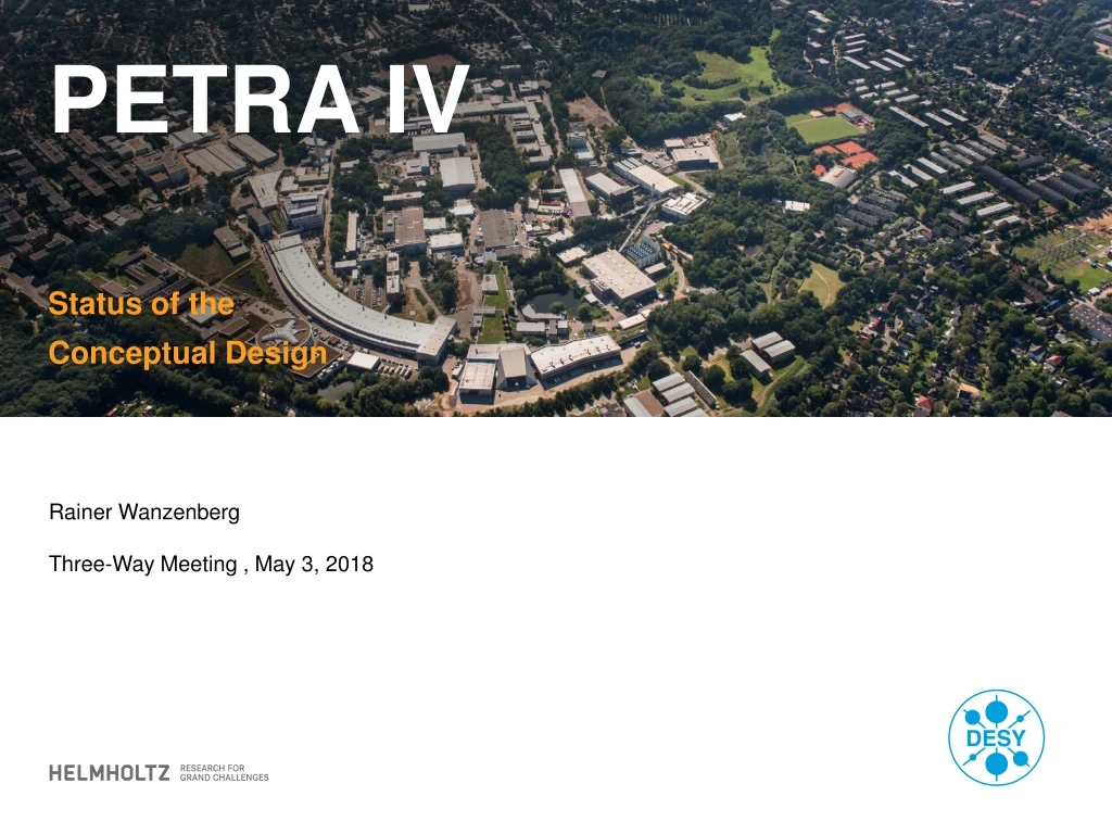
PETRA IV Status of the Conceptual Design Rainer Wanzenberg Three-Way Meeting , May 3, 2018
Outline • PETRA IV schedule and timeline • CDR preparation phase • Status of the Lattice Design • PETRA IV Injector • Technical implications • Collaborations
PETRA IV – first conceptual ideas in 2016 Parameters and parameter range, status February 2016: Goals: 2024 Start construction 2026 Start up PETRA IV Science case: Understanding the Complexity of Nature Bright, Tailored X-Rays, 3D Imaging
PETRA IV – Updated schedule • Adjustment of the schedule • an update of the national roadmap - initially expected for end of 2018 / 2019 - • is now scheduled for 2021 • more time for the accelerator design studies • evaluate promising alternative lattice concepts, • optimization between minimum achievable emittance and dynamic aperture, • sensitivity to errors , and aspects related to a stable operation of the ring • Current activities • CDR preparation phase • finish CDR until spring 2019 • CDR includes science case anddesign concept of machine and beamlines • (science case will be ready already in 2018)
PETRA IV – New Timeline roadmap proposal bring PETRA IV onto the national roadmap of large-scaleresearch facilities (next call: 2021) Goal:
Design Strategy Lattice Design Design goal: get an large dynamic acceptance (ideal case: off-axis injection is possible) • design based on a hybrid seven bend achromat (scaled from ESRF-EBS cell) • option: DMI / FODO style undulator cell • arc cell with phase advance of p between sextupoles, double -I cell (DMI) • (first approch with: double twist in 4D-phase to enable chromatic correction in both planes) • cell for insertion devices, FODO-like Design goal: reuse most parts of injector chain Injectors • studies to improve emittance, including a new lattice for the synchrotron • investigation of the technical requirements to maintain operation until 2045 Investigation of the technical limits and possibilities at an early stage before a lattice design is finalized Technical design • magnet design: design studies of quads, sextupoles, combined function magnets • and dipoles with longitudinal gradient • girder design: investigation of concepts with new materials, • studies of alignment and installation concepts • vacuum design: modeling of the system with small chambers • fast kickers: on axis injection
PETRA IV – Lattice design status Hybrid Seven Bend Achromat scaled and adopted from ESRF-EBS 8 cells / arc (cell length: 25.2 m / new version ~ 26 m), injection in one long straight section, damping wigglers in another straight section Contribution to IPAC 2018: J. Keil, et al.A PETRA IV LATTICE BASED ON HYBRID SEVEN BEND ACHROMATS Paper submitted to JSR: C. G. Schroer, et al. PETRA IV: The ultra-low emittance source project at DESY
PETRA IV – “Reference lattice”, H7BA Nat. emittance 0 =9.3 pm Damping Wigglers Injection βx=100 m sensitivity to errors (2 mm rms, all magnets, no correction): • RF: 500 MHz, 6 MV, bucket height=3.3% • Ax = 1.35 mm·mradDynamic acceptance • Ay= 1.24 mm·mrad(6 D tracking, no errors) The DA is reduced by a factor 2 with respect to the ideal one • an on axis injection seems to be required for a safe injection (with errors)
Intra beam scattering 80 bunches 50 pm 960 bunches, 20 pm εx εy Intra beam scattering: Multiple Coulomb scattering, theory by A. Piwinski (1974) Beam intensity • Using 1920 bunches (not equally spaced) would imply • 200 mA operation with the same parameters or • 100 mA operation with an emittance of 16 pm • First estimates indicate that the total current in the timing mode will be only 80 mA due to collective effects
PETRA IV – recent lattice design studies • H7BA – ESRF style lattice • 8 cell / arc , cell length 26.2 m • + 4 undulator cells in the long • straight sections • canting in 4 insertion straigths brightness: 10 m long undulator in the long straight section with optimized beta-function ( 2 m).
Updated “Reference lattice” H7BA 4 High brightness IDs Injection without IBS v. Lauehall New hall PXE PXN 26 insertion devices: 8 x L=2 m (canted) 18 x L=5 m (straight)λp = 32 mm, B0 = 0.91 T two octants: 2 x (7+1) = 16 beam lines two extensions: 2 x (2x2+1) = 10 beam lines undulator beam lines (total) 26 beam lines + side beam lines IBS with IDs qb = 0.8 nC ex,y = 33 / 3.3 pm rad 2 = canting (4 mrad) 1 = straight section (low beta)
Low beta cells and canted cells canting β* = 2 m • Request by users: Four IDs in the long/short straight sections with optimized beta functions to achieve high brightness • Upstream of the existing halls and the new hall; ID length 5 m and/or 10 m • Additional chromaticity due to the small β* → increase in sextupole strength • Extension halls PXE and PXN: First two ID straights are canted straights, 4 mrad Work in progress: impact of the canting on emittance and energy spread smaller dynamic aperture due to low beta insertion and canting
Options: DMI Lattice / FODO Type cell x,y = DMI - cell FODO type undulator cells 2 3 1 1 2 4 6 5 Two cell types: Non interleaved double –I cell (no IDs), FODO type undulator cells (cells with IDs) emittance ~ 30 pm Work in progress: preliminary results indicate: large dynamic aperture (~ 18 mm at b ~ 100 m) off axis injection seems to be possible
PETRA IV – Collective effects • Impedance budget • Timing mode TMCI threshold • effective impedance budget 1.2 MW/m • work in progress: • Impedance model • geometric impedance • 22 insertion device sectors (low gap chambers) • ~ 10 BPMs / cell • ~ 5 absorbers, bellows, flanges / cell • ~ 40 cavities ~ 0.5 MW/m • resistive wall impedance • NEG coated chamber • modelling with IW2D code *), CERN *) N. Mounet, “The LHC transverse coupled-bunch instability”, Ph.D thesis, Lausanne, EPFL, 2012. Contribution to IPAC 2018: Yong-Chul Chae , et al. Status of Impedance Modeling for PETRA IV
PETRA IV – Injector Linac II S-Band Linac (450 MeV) PIA (accumulator ring) DESY II 450 MeV 7 GeV, Emittance (6 GeV) x/y ~ 350/15 nm Intensity: max. 2 x 10¹⁰, (bunch current in 0.42 mA in PETRA III) Study: new booster DESY IV One octant of DESY IV Contribution to IPAC 2018: Hung-Chun Chao, et al. Lattice Studies of a Booster Synchrotron for PETRA IV
Technical implications Design Strategy • Collaboration with Efremov Institute • design of high gradient magnets • Contacts to industry (Thyssen Krupp) concerning magnet materials • Collaboration with Alfred Wegener Institute master thesis on bionic girders, Ph. D. thesis Magnets, Girder • Simulations, using: MAX IV chamberprofile + NEG • Plans for an experiment at PETRA III delayed due to a lack ofresources Vacuum System • Collaborationwith • Technische Universität Darmstadt, TEMF, • investigationof 500 MHz singlecellcavities • (masterthesisisplanned) • high precision BPMs, …, hot swap power supplies, study of conceptual ideas RF System Diagnostics … Power supplies
Magnets QHG20 • Collaboration with Efremov Institute • Design study for Sextupole magnets • presently factor 2.5 stronger as ESRF-EBS • Building of prototypes QHG20 • with different materials HERA steel One quarter of an iron joke of a QHG20 prototyp quadrupole build at DESY (pole design from Efremov Inst.) The coils are build at Efremov Inst. (delivery at end of May) Goal: first prototype ready in summer 2018 HERA steel
Girders • Collaboration with Alfred Wegener Institute: Bionic Lightweight Design of Girders The AWI explores the principles that turn the exoskeletons (shells) of unicellular planktonic organisms into extremely light and stable constructions. (https://www.awi.de/en/science/special-groups/bionics.html) master thesis by Simone Andresen: investigation of a reference girder, simplified model of a PETRA III girder Optimization of the structure using an evolution strategy to improve the stiffness and vibration characteristics Girder Bases Magnet cylinders Topological optimized structure: Modal analysis Front surfaceis suppressed
Mechanical stability Building monitoring At five positions in the PETRA tunnel reflecting marks have been placed at the tunnel walls (WR20, NR60, OR60, SOL85, SWR20). photogrammetry is used to determine long-term movement of the tunnel building • preliminaryresults: • difference 6.2.18 (shut down) 4.4.2018 • dZlongt., dXhorz., dYvert • NR60, dZ = 2.0mm, dX = 0.1mm, dY = 0.3mm • OR60, dZ = 1.2mm, dX = 0mm, dY = 0mm • SOL86, dZ = 1.7mm, dX = 0.2mm, dY = 0.3mm • SWR20, dZ = 1.7mm, dX = 0.2mm, dY = 0.3mm • WR20, dZ = 0.5mm, dX = 0.0 mm, dY = 0.0 mm
Vacuum System Experience at DESY: -MVS- NEG-sputtering facility 80 m of damping wigglers with NEG coated low gap chambers PLANNED EXPERIMENTS: PETRA III ARC SECTION • Install NEG-coatedchambers in standardarc-section in PETRA III • 13 sputter coated standard dipole chambers • optionally: 8 NEG-coated quadrupol-chambers Tostudy: • Photons hitting the walls may lead to a self-activation of the NEG material ? Could avoid in situ heating of the chambers. • How fast will thisprovidesufficientpressurelevel ? • Conditioningofventedsection? • different coatings: standardcolumnar-film anddensity-film The installation of the chambers into PETRA III is planed for the winter shut-down 2018/19
RF System Two variants have been considered 500 MHz or 100 MHz System Many bunches are advantageous for the brightness mode 500 MHz harmonic number h = 3840 1920 bunches (4 ns bunch to bunch spacing) seems to be possible. One cell cavity (BESSY), RS = 3 MW, 30 kW, 0.4 MV Total voltage 6 MV requires at least 15 cavities 3rd harmonic cavities, ~ 2 MV, 22 mm long bunches mitigation of IBS for the timing mode (80 bunches x 1 mA) 100 MHz cavity MAX IV design Collaboration with Technische Universität Darmstadt, TEMF Herbert De Gersem, Wolfgang Ackermann, Wolfgang O. Müller Cavity parameters, HOM calculations, etc. now also for the 500 MHz cavity Damped single cell 500 MHz cavity F. Marhauser, E. Weihreter, BESSY II
Collaborations • ESRF supporting the lattice design, sharing lattice files visit to ESRF (June) , visitor (Simone Liuzzo) from ESRF at DESY (Aug.) • Mikael Eriksson joined the PETRA IV project preparation as a generalist from June 2016 • SLAC – DESY collaboration visit to SLAC in Oct 2016 Yunhai Cai visited DESY in April 2017, LEGO, lie algebra methods • Efremov institute - DESY collaboration: magnet design • Alfred Wegener institute - DESY collaboration: girder design, Ph.D. thesis • Technical University of Darmstadt: RF calculation, 500 MHz cavity, master thesis