Download
1 / 15
170 likes | 512 Views
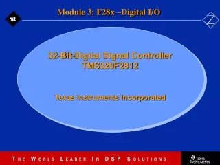
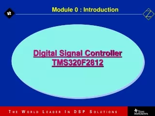
Module 1 : Architecture. Digital Signal Controller TMS320F2812. Texas Instruments Incorporated European Customer Training Center University of Applied Sciences Zwickau (FH). C281x Block Diagram. Event Manager A. Program Bus. Event Manager B. Sectored Flash. RAM. Boot ROM.

E N D
Module 1 : Architecture Digital Signal Controller TMS320F2812 Texas Instruments Incorporated European Customer Training Center University of Applied Sciences Zwickau (FH)
C281x Block Diagram Event Manager A Program Bus Event Manager B Sectored Flash RAM Boot ROM 12-bit ADC Watchdog 22 A(18-0) 32 McBSP 32 D(15-0) 32 CAN2.0B PIE Interrupt Manager R-M-W Atomic ALU 32x32 bit Multiplier 32-bit Auxiliary Registers SCI-A SCI-B 3 32 bit Timers SPI Realtime JTAG Register Bus CPU GPIO Data Bus
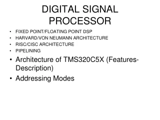
C28x CPU • MCU/DSP balancing code density & execution time. • Supports 32-bit instructions for improved execution time; • Supports 16-bit instructions for improved code efficiency Program Bus • 32-bit fixed-point DSP • 32 x 32 bit fixed-point MAC • Dual 16 x 16 single-cycle fixed-point MAC (DMAC) • 32-/64-bit saturation • 64/32 and 32/32 modulus division • Fast interrupt service time • Single cycle read-modify-write instructions • Unique real-time debugging capabilities • Upward code compatibility PIE Interrupt Manager R-M-W Atomic ALU 32x32 bit Multiplier 32-bit Auxiliary Registers 3 32 bit Timers Register Bus Realtime JTAG CPU Data Bus
C28x Multiplier and ALU / Shifters Program Bus 32 Data Bus 16/32 XT (32) or T/TL 16 8/16/32 MULTIPLIER 32 x 32 or Dual 16 x 16 32 Shift R/L (0-16) P (32) or PH/PL 8/16 32 32 32 Shift R/L (0-16) 32 32 ALU (32) 32 ACC (32) AH (16) AL (16) AH.MSB AH.LSB AL.MSB AL.LSB • 32 Shift R/L (0-16) 32 Data Bus
Data Bus Program Bus XAR0 XAR1 XAR2 XAR3 XAR4 XAR5 XAR6 XAR7 DP (16) ARAU Data Memory C28x Pointer, DP and Memory 6 LSB from IR 22 32 MUX MUX XARn 32-bits ARn 16-bits
DP @X C28x Internal Bus Structure Program Program Address Bus (22) Program (4M* 16) PC Program-read Data Bus (32) Decoder Data-read Address Bus (32) Data (4G * 16) Data-read Data Bus (32) Memory Registers Execution Debug ARAU Real-Time Emulation & Test Engine MPY32x32 SP R-M-W Atomic ALU ALU Standard Peripherals External Interfaces JTAG XT XAR0 to XAR7 P ACC Register Bus / Result Bus Data/Program-write Data Bus (32) Data-write Address Bus (32)
LOAD READ • Atomic Instructions Benefits: • Simpler programming • Smaller, faster code • Uninterruptible (Atomic) • More efficient compiler Registers ALU / MPY Mem CPU WRITE STORE Standard Load/Store Atomic Read/Modify/Write DINT EINT MOV AL,*XAR2 AND AL,#1234h MOV *XAR2,AL AND *XAR2,#1234h 2 words / 1 cycles 6 words / 6 cycles C28x Atomic Read/Modify/Write
W A B C W F1 F2 D1 D2 R1 R2 X F1 F2 D1 D2 R1 R2 X F1 F2 D1 D2 R1 R2 X F1 F2 D1 D2 R1 R2 X F1 F2 D1 D2 R1 R2 X F1 F2 D1 D2 R1 R2 X F1 F2 D1 D2 R1 R2 X F1 F2 D1 D2 R1 R2 X W W D E F G W W W W R1 R2 XW D2 R1 R2 X W C28x Pipeline 8-stage pipeline E & G Access same address H F1: Instruction Address F2: Instruction Content D1: Decode Instruction D2: Resolve Operand Addr R1: Operand Address R2: Get Operand X: CPU doing “real” work W: store content to memory Protected Pipeline • Order of results are as written in source code • Programmer need not worry about the pipeline
Data | Program Data | Program 0x00 0000 MO SARAM (1K) 0x00 0400 M1 SARAM (1K) reserved 0x00 0800 PF 0 (2K) reserved 0x00 0D00 PIE vector (256) ENPIE=1 reserved 0x00 2000 XINT Zone 0 (8K) reserved 0x00 1000 0x00 4000 XINT Zone 1 (8K) 0x00 6000 reserved PF 2 (4K) 0x00 7000 reserved PF 1 (4K) 0x00 8000 reserved LO SARAM (4K) 0x00 9000 L1 SARAM (4K) 0x08 0000 XINT Zone 2 (0.5M) reserved 0x00 A000 0x10 0000 XINT Zone 6 (0.5M) 0x3D 7800 OTP (1K) 0x18 0000 reserved 0x3D 8000 FLASH (128K) reserved 0x3F 8000 HO SARAM (8K) 0x3F A000 reserved 0x3F C000 XINT Zone 7 (16K) MP/MC=1 0x3F F000 Boot ROM (4K) MP/MC=0 CSM: LO, L1 OTP, FLASH 0x3F FFC0 XINT Vector-RAM (32) MP/MC=1 ENPIE=0 BROM vector (32) MP/MC=0 ENPIE=0 TMS320F2812 Memory Map 0x3D 7C00 128-Bit Password
Prevents reverse engineering and protects valuable intellectual property 128-bit user defined password is stored in Flash 128-bits = 2128 = 3.4 x 1038 possible passwords To try 1 password every 2 cycles at 150 MHz, it would take at least 1.4 x 10²³ years to try all possible combinations! 0x00 8000 0x00 9000 0x00 A000 0x3D 7800 OTP (1K) LO SARAM (4K) 0x3D 8000 FLASH (128K) L1 SARAM (4K) 128-Bit Password reserved reserved Code Security Module 0x3D 7C00
PIE Register Map PIE module For 96 interrupts Peripheral Interrupts 12x8 = 96 28x CPU Interrupt logic INT1 to INT12 12 interrupts 28x CPU IFR IER INTM 96 Auto Context Save T ST0 AH AL PH PL AR1 (L) AR0 (L) DP ST1 DBSTAT IER PC(msw) PC(lsw) C28x Fast Interrupt Response Manager • 96 dedicated PIE vectors • No software decision making required • Direct access to RAM vectors • Auto flags update • Concurrent auto context save
C28x / C24x Modes Mode Type Mode Bits Compiler Option OBJMODE AMODE C24x Mode 1 1 C28x Mode 1 0 Test Mode (default) 0 0 Reserved 0 1 -v28 -m20 -v28 -v27 • C24x source-compatible mode: • Allows you to run C24x source code which has been reassembled using the C28x code generation tools (need new vectors) • C28x mode: • Can take advantage of all the C28x native features
Reset OBJMODE=0 AMODE=0 ENPIE=0 VMAP=1 Bootloader sets OBJMODE = 1 AMODE = 0 Reset vector fetched from boot ROM 0x3F FFC0 Execution Entry Point H0 SARAM Boot determined by state of GPIO pins Reset – Bootloader XMPNMC=0 (microcomputer mode) Note: Details of the various boot options will be discussed in the Reset and Interrupts module
High performance 32-bit DSP 32 x 32 bit or dual 16 x 16 bit MAC Atomic read-modify-write instructions 8-stage fully protected pipeline Fast interrupt response manager 128Kw on-chip flash memory Code security module (CSM) Two event managers 12-bit ADC module 56 shared GPIO pins Watchdog timer Communications peripherals Summary