Download
1 / 36
490 likes | 1.27k Views
Transmission Electron Microscopy. David Stokes 2DX Workshop University of Washington 8/15-8/19/2011. TEM transmissive resolution determined by optics analogous to bright field light microscope detector is film or CCD SEM reflective, surface imaging

E N D
Transmission Electron Microscopy David Stokes 2DX Workshop University of Washington 8/15-8/19/2011
TEM transmissive resolution determined by optics analogous to bright field light microscope detector is film or CCD SEM reflective, surface imaging resolution determined by spot size x-ray microanalysis or EELS possible STEM transmissive, small spot with scan coils resolution determined by spot size analogous to confocal detector is PMT x-ray microanalysis or EELS possible Kinds of Electron Microscopes
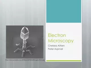
TEM metal shadowed molecules 250 nm
Source of electrons Tungsten: - outer electrons of W are made free by heating the metal. - W has excellent yield when heated just below its melting temp of 3653K. - Heat to 2600K for good yield without melting and evaporating tip (saturation point) - 100 hrs with W wire. - Make filament (cathode) at neg potential (e.g. -100 kV). - As electrons boil off the W, they are repelled by the cathode. - Potential difference relative to the anode provides the accelerating voltage - Make Weihnolt several hundred volts more negative electrons pass through the aperture in the Weihnolt cap. bias controls output of electrons and shapes field - Anode is grounded so electrons are accelerated towards it. - Electrostatic field causes crossover at the anode - this is effective source size LaB6 - has lower work function: amount of energy necessary to free electrons. - 1000K with higher electron yield and longer life. - get small beam crossover size with high flux (10x emission of W) Field emission - single crystal of W oriented relative its xtal lattice - no heating - series of high voltage anodes draw electrons out of lattice - electrostatic lens of anodes -> 10 nm source size - need very high vacuum -> contamination - Zirconium to reduce work function, heating to reduce contamination
Properties of Electrons Energy of electrons is work W required to move electron from anode to cathode against force F=-eE: U=accelerating voltage charge on electron is -1.602x10⁻¹⁹ Coulombs, when accelerated through 1V potential difference has kinetic energy of 1.602x10⁻¹⁹ Nm (joule) define this kinetic energy as 1 eV. With accelerating voltage of 200kV – electrons have energy of 200keV (= 3.2x10⁻¹⁴ joules) compare to C-C bond of 5.8x10⁻¹⁹ joules (3.6 eV) or lattice binding energy of 1-2 eV Speed of electrons at 100kV: v=1.64x10⁸m/sec more than 1/2 speed of light Have to consider relativity 1MeV = 2Eo m=3m0 Wavelengths of electrons () 0.0349 Å at 120kV, 0.025 Å at 200 kV, 0.01969 Å at 300 kV diffraction limit for resolution of any optical system: D = /2 compare with wavelength of light: 2000 Å or X-rays: 1.5 Å for Cu K 1 Å synchrotron radiation
Force on an electron electrostatic: electromagnetic:
Typical electron lenses single lens (e.g. condensor) split lens (e.g. objective)
Magnetic lenses like Glass lenses are governed by Newton’s lens equation http://members.shaw.ca/quadibloc/science/opt05.htm and
Focal length of Electromagnetic lens f = focal length K = lens const, U = voltage, i = current electromagnetic lens: can change focal length by changing current glass lens: change focus by moving specimen up and down change magnification by switching lenses
Lens Strength affects focal length f = focal length K = lens const, U = voltage, i = current A stronger lens demagnifies the image!!!
Trajectory of electrons through a homogeneous B field where is angle between v and B Energy of electron conserved – no change in |v| If force is to v: electron moves in a circle If force is || to v, path unchanged. Generally, path is spiral, with v|| and v components So electrons passing through given point P will intersect again at point P' • PP' = v||Tc = vTccos, • where Tc is time to complete circle, • which is independent of P If many angles focused in same plane, get image formed For small angles of , cos ~1 and get image formed at P'. Larger angles of reduces the distance to P' (cos = (1 - 2/2 + . . .) and thus gives rise to spherical aberration P'
Real lens is non-homogeneous field - so-called bell-shaped field Aberrations: astigmatism, coma, spherical, field curvature, distortion (pincushion/barrel) chromatic and Contrast Transfer Function
TEM lens configuration Condenser Lenses: Demagnifies source Define “spot size” Objective lens: Defines image focus Has fixed magnification (20-50x) Intermediate lens: Controls whether Image or diffraction pattern Is recorded Projector lenses: Controls image magnification or Diffraction “camera length”
Condenser lenses C1 lens produces image of source C2 lens demagnifies onto sample C2 aperture reduces beam currentand makes beam more parallel
C1 lens controls spot size Strong C1 lens produces small probe size and weak beam Weak C1 lens produces larger probe size and bright beam This is known as “spot size” C1 crossover produces image of source and Mag = u/v for C2 lens
Beam convergence Increasing strength of C2 lens Upper Objective lens ~parallel convergent divergent parallel
magnification of objective: 20-50x angle for 2.5 Å resolution at 200kv: = /d = 0.025/2.5 = 10 mrad = 0.5° most of mag range achieved with projection lenses Much smaller angles and aberrations therefore less important
Diffraction vs. Imagingcontrolled by Intermediate lens Back focal plane of objective lens corresponds to diff pattern Selected area aperture is at first image plane Intermediate lens selects either BFP or 1st image plane as its object Diff pattern or 2nd image serves as object for projector lens
Coma For high resolution images, you want the apparent source aligned with the real source on the optical axis and the beam to run parallel to this axis. This is coma-free alignment.
Deflectors Deflectors produced by transverse fields: E field (parallel plate capacitor) B field (electromagnetic lens) electrostatic electromagnetic
deflector coils generally come in pairs gun tilt coils pivot points aligned pivot points misaligned
Apertures source condensor lens condensor aperture specimen
A typical scattering event i s • Proportionality constant for scattering: • is scattering cross-section for one atom (cm2/atom) • elastic, inelastic, absorption, fission
F R F + + + + + + + + b z Electron Scattering Elastic Scattering: Rutherford scattering electrostatic force: Z = atomic number, but, actually need to consider screening of electrons on nuclear charge Solving Scrodinger’s equation for the potential and making approximations for screening of nuclear charge by electron cloud: N.B. Elastically scattered electrons have same wavelength as incident beam and are most effective for generating phase contrast image because they interfere with the unscattered beam
Inelastic Scattering Energy transferred from incident electrons to the specimen • Oscillations of molecular bonds and phonon excitations: 20 meV – 1 eV • too small to generally observe given ~1 eV spread of beam energy • Excitation of outer electrons and valence/conduction band electrons (metals): 1-50 eV • 3. Ionization of inner electrons (K,L,M shells) to unoccupied shells: 10 – 100s eV
Why do we hate inelastic collisions? Inelastic electrons are focused at “undesirable” places And therefore produce a blurred image due to Chromatic aberration Inelastic scattering produces chemical changes radiation damage
differential cross-section total scattering cross-section scattered outside 2.4 A aperture unscattered inelastics within aperture differential scattering vs. 25 keV electrons with Ar gas elastics within aperture
The inelastic scattering “blurs” the low spatial frequencies electrons X-rays
But they can be filtered out (after they damaged the specimen) -filter +filter