Lecture #3 EGR 110 – Engineering Graphics
90 likes | 259 Views
Lecture #3 EGR 110 – Engineering Graphics. Engineering Design Process

Lecture #3 EGR 110 – Engineering Graphics
E N D
Presentation Transcript
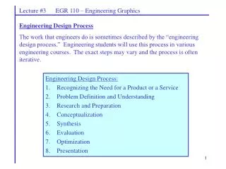
Lecture #3 EGR 110 – Engineering Graphics Engineering Design Process The work that engineers do is sometimes described by the “engineering design process.” Engineering students will use this process in various engineering courses. The exact steps may vary and the process is often iterative. • Engineering Design Process: • Recognizing the Need for a Product or a Service • Problem Definition and Understanding • Research and Preparation • Conceptualization • Synthesis • Evaluation • Optimization • Presentation
Lecture #3 EGR 110 – Engineering Graphics Engineering Design Process Many stages of the engineering design process will involve the need for drawings and for analysis. EGR 110 introduces two powerful tools that will be very useful in the engineering design process: • AutoDesk Inventor • Produce solid models of parts • Produce assembly drawings showing how the parts fit together • Produce detailed drawings • Use parametric modeling features to easily modify designs and to explore new solutions • Use constraints to insure proper dimensioning • Use constraints to test motion of moving parts • MatLab • Perform various types of analysis • Graph results to illustrate performance as parameters vary
Lecture #3 EGR 110 – Engineering Graphics • Engineering Design Process: • Recognizing the Need for a Product or a Service • Problem Definition and Understanding • Sketching and CAD used for preliminary drawings • Research and Preparation • Conceptualization • CAD (especially parametric modeling software) allows the designer to easily modify designs and experiment with new concepts. • MatLab used for calculations related to various types of designs • Synthesis (or design) • MatLab used to achieve desired design objectives. • CAD used to work out the exact details of the design. Specify and verify dimensions, tolerance, range of motion, etc. • Evaluation • CAD and MatLab used to evaluate performance. • Use CAD to interface with machines (CAD/CAM) • Optimization • Use CAD to adjust design parameters to improve performance. • Use MatLab to perform calculations to improve performance • Presentation • CAD used to produce final part and assembly drawings. • MatLab used for final performance analysis of product.
Lecture #3 EGR 110 – Engineering Graphics Drawings are used at various stages in the engineering design process. Reference: Engineering Graphics Text and Workbook, Series 1.2, by Craig & Craig.
Lecture #3 EGR 110 – Engineering Graphics Different types of drawings have different purposes. Reference: Engineering Graphics Text and Workbook, Series 1.2, by Craig & Craig.
Lecture #3 EGR 110 – Engineering Graphics Assembly drawings show how the parts are used, how the parts are assembled, and part identifications. This is typically the first drawing in a set of drawings. Assembly drawings are often included with the product for reference. An exploded view may be used to identify parts for replacement and to show how to disassemble and reassemble for servicing. Reference: Engineering Graphics Text and Workbook, Series 1.2, by Craig & Craig.
Lecture #3 EGR 110 – Engineering Graphics Production drawings (or detail part drawings or working drawings) must convey all information needed to produce the part. Features of the drawing include different views of the part, dimensions, notes, materials, and a title block. Reference: Engineering Graphics Text and Workbook, Series 1.2, by Craig & Craig.
Lecture #3 EGR 110 – Engineering Graphics Group design project The purpose of the group design project is to give the student experience in the various stages of the engineering design process. For details of this semester’s design project, see the assignment sheet provided by the instructor.


