Download

1 / 39
390 likes | 632 Views
Module 9002 Heat Transfer and Heat Exchangers. Heat Exchangers. Heaters (sensible heat changes) Coolers (sensible heat changes) Condensers (also change of state, V to L) Evaporators (also change of state, L to V). Types of Heat Exchanger. Shell and tube Double pipe Plate

E N D
Module 9002Heat Transfer and Heat Exchangers Paul Ashall, 2008
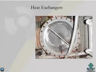
Heat Exchangers • Heaters (sensible heat changes) • Coolers (sensible heat changes) • Condensers (also change of state, V to L) • Evaporators (also change of state, L to V) Paul Ashall, 2008
Types of Heat Exchanger • Shell and tube • Double pipe • Plate • Finned tubes/gas heaters • spiral • Vessel jackets • Reboilers and vapourisers/evaporators Etc • Direct/indirect Paul Ashall, 2008
Uses in chemical processes • Chemical reactors (jackets, internal heat exchangers/calandria) • Preheating feeds • Distillation column reboilers • Distillation column condensers • Air heaters for driers • Double cone driers • evaporators • Crystallisers • Dissolving solids/solution • Production support services – HVAC, etc • Heat transfer fluids • etc Paul Ashall, 2008
continued Important consideration in: • Scale-up i.e. laboratory scale (‘kilo lab’) to pilot plant scale (250 litres) to full plant scale operation (10000 litres) • Energy usage and energy costs • Process design and development Paul Ashall, 2008
Heat transfer fluids • Steam (available at various temperatures and pressures) • Cooling water (15oC) • Chilled water (5oC) • Brines (calcium chloride/water fp. -18 deg cent. at 20% by mass; sodium chloride/water fp. -16.5 deg cent. at 20 % by mass) • Methanol/water mixtures • Ethylene glycol/water mixtures • Propylene glycol/water mixtures (fp. -22 deg cent at a concentration of 40% by mass) • Silicone oils (‘syltherm’) Paul Ashall, 2008
Low temperature heat transfer fluids Considerations: • Temperature(s) required • Freezing point • Viscosity • Specific heat • Density • Hazardous properties Paul Ashall, 2008
Mechanisms for heat transfer • Conduction • Convection • Radiation Driving force for heat transfer is temperature difference. Heat will only flow from a hotter to a colder part of a system. Paul Ashall, 2008
Heat transfer by conduction Fouriers law dQ/dt = -kA(dT/dx) dQ/dt – rate of heat transfer k – thermal conductivity A – area perpendicular to direction of heat transfer, x dT/dx – temperature gradient in direction x Paul Ashall, 2008
Heat transfer by conduction (steady state) Q = kmA (ΔT/x) or q = km (ΔT/x) q –heat flux, J/s m-2 Q - rate of heat transfer, J/s km – mean thermal conductivity, A – area perpendicular to the direction of heat transfer, m2 ΔT – temperature change (T1 – T2), K x – length, m Paul Ashall, 2008
Thermal conductivity, k Paul Ashall, 2008
Conductive heat transfer through adjacent layers Paul Ashall, 2008
Example Paul Ashall, 2008
Conduction of heat through cylindrical vessels Q = k2πLΔT/ln(r2/r1) L – length of tube/cylinder r2 external radius r1 internal radius Paul Ashall, 2008
AL , log mean wall area Q = kmAL (T1 – T2) r2 – r1 where AL= 2πL (r2 – r1) ln(r2/r1) Paul Ashall, 2008
Boundary layers and Heat transfer coefficients Paul Ashall, 2008
Determination of overall heat transfer coefficient Paul Ashall, 2008
Example – calculation of U Paul Ashall, 2008
‘thin walled tube’approximation Assumptions: • Thin wall and therefore xw is small and since k is large, term xw/kALis negligible compared to other terms • Also A terms cancel as they are approximately equal 1/U = 1/h1 + 1/h2 Paul Ashall, 2008
Fouling factors Heat transfer surfaces do not remain clean. They become contaminated with dirt, scale, biofilms etc. This has the effect of reducing the overall heat transfer coefficient and reducing the rate of heat transfer. We take account of this by adding a term 1/Ahd for each deposit to the equation for the overall heat transfer coefficient, U, where hd is the fouling factor for the deposit and A is the corresponding area term. They represent an additional resistance to heat transfer.This will have the effect of reducing U and therefore Q. Paul Ashall, 2008
Heat flow (duty) Q = hAΔT or Q = UAΔT Paul Ashall, 2008
Sensible heat changes Q = mcpΔT m mass flow, kg/s Cp specific heat J kg-1 K-1 ΔT change in temperature of fluid Paul Ashall, 2008
Evaporators/condensers Paul Ashall, 2008
Enthalpy balance Enthalpy lost by hot fluid = enthalpy gained by cold fluid (Assume negligible heat losses to surroundings) Paul Ashall, 2008
Simple double tube single pass heat exchanger • Co-current operation • Counter-current operation • Temperature profiles • LMTD Paul Ashall, 2008
Heat exchanger duty Q = UAθlmtd Paul Ashall, 2008
Examples Paul Ashall, 2008
Multi pass shell and tube heat exchangers • LMTD correction factor, F • LMTD value used is that for counter current flow with same fluid inlet/outlet temperatures Q = UAθlmtdF Paul Ashall, 2008
Example – double pass T1 t1 t2 T2 T1 = 455K; T2 = 388K; t1 = 283K; t2 = 372K Paul Ashall, 2008
continued P = (372 – 283)/(455 – 283) = 0.52 R = (455 – 388)/(372 – 283) = 0.75 Therefore F= 0.87 (from graph) To obtain maximum heat recovery from the hot fluid, t2 must be as high as possible. T2 – t2 is known as the approach temperature. Paul Ashall, 2008
Dittus-Boelter equation Used for calculating h values in circular tubes under turbulent flow conditions. Nu = 0.023 Re0.8 Pr 0.4 Paul Ashall, 2008
Simple design Paul Ashall, 2008
Non-steady state processes Paul Ashall, 2008
Heat transfer by radiation q = eσ(T14 – T24) q – heat flux e – emissivity (0 to 1) – typically 0.9 σ – Stefan-Boltzmann const.(5.67 x 10⁻⁸ W m-2 K-4) T1 – temp. of body (K) T2 – temp. of surroundings Paul Ashall, 2008
Example Paul Ashall, 2008
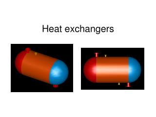
Types of heat exchanger – shell & tube • Passes • shell • Multiple tubes • Baffles • Co- and counter current operation Paul Ashall, 2008
Plate • Individual separated thin corrugated parallel s.s. plates • Gaskets separate plates • Gap approx. 1.4mm • Plate and frame arrangement • High h values at relatively low Re values and low flow rates • Can operate with small ΔT • Reduced fouling • Easy cleaning Paul Ashall, 2008
Finned tubes • Radial fins • Longitudinal fins • For air/gas heaters where film heat transfer coefficients on gas side will be very low compared with condensing steam on the other side of tube. Rate of heat transfer is increased by increasing surface area on side of tube with the limiting (low) heat transfer coefficient (gas side). Paul Ashall, 2008
References • An Introduction to Industrial Chemistry, Ed. C. A. Heaton • Concepts of Chemical Engineering 4 Chemists, Ed. S. Simons, RSC, 2007 • Unit Operations of Chemical Engineering, W. L. McCabe et al • Chemical Engineering Vol. 1, Coulson & Richardson • Heat Transfer, R. Winterton • Introduction to Heat Transfer, F. P. Incropera & D. P. DeWitt • Ullmans Encyclopedia of Industrial Chemistry • Engineering Thermodynamics Paul Ashall, 2008