Download
1 / 26
290 likes | 767 Views
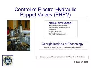
George W. Woodruff School of Mechanical Engineering. HUSCO Electro-Hydraulic Poppet Valve Project Review. Presented by :. PATRICK OPDENBOSCH. AGENDA. Components Opening Sequence Related Work Mathematical Modeling Control Schemes Future Work Conclusions. Input. Pilot Spring. Pilot.

E N D
George W. Woodruff School of Mechanical Engineering HUSCOElectro-Hydraulic Poppet Valve Project Review Presented by: PATRICK OPDENBOSCH April 07, 2003
AGENDA • Components • Opening Sequence • Related Work • Mathematical Modeling • Control Schemes • Future Work • Conclusions
Input Pilot Spring Pilot Solenoid Core Control Chamber Main Spring Feed Line Main Poppet Inlet Outlet 1. COMPONENTS
3. RELATED WORK Performance Limitations of a Class of Two-Stage Electro-hydraulic Flow Valves1 • Done by: Rong Zhang. Dr. Andrew Alleyne. Eko Prasetiawan. Figure 3.1 Vickers EPV-16 Valvistor (1) Zhang, R.,Alleyne, A., and Prasetiawan, E., “Performance Limitations of a Class of Two-Stage Electro-hydraulic Flow Valves”, International Journal of Fluid Power, April 2002.
Valve Modeling: States: (3.1) Output: . (3.2) Figure 3.2 Electro-proportional flow valve (3.3)
Jacobian Linearization and Model Reduction : (3.4) Assumptions: (3.5) (3.6) (3.7)
(3.8) Figure 3.3 Simplified Second Order Model Figure 3.4 Flow valve identification test setup
Figure 3.6 Root-locus of a Valvistor-controlled system Figure 3.5 Time domain experimental validation • Main Results: • Pilot flow introduces open-loop zeros that limit the closed-loop bandwidth. • Pilot flow can be re-routed to tank trading performance by efficiency. • Open-loop zeros can be moved leftwards by altering valve parameters.
4. MATHEMATICAL MODELING • Flow Distribution: uv Q2 Qp Qa Q1 Qb
Dr xm Q2 Pp Pa xm Q1 Pb Pa (4.2) (4.1) xp Pp xm Qp Pb (4.3)
small small small • Compressibility: (4.4) am,1 xp (4.5) xm Q2 xo (4.6) (4.7) Qp (4.8) r : Fluid density V: Chamber volume e : Equivalent length of pilot inside control volume b : Bulk modulus (4.9) (4.10)
Second Order Systems: Pilot Dynamics (from equilibrium state): (4.11)
Main Poppet Dynamics (from equilibrium state): am,1 : Poppet’s Large area am,s : Poppet’s Small area (4.12)
Letting: and (4.13) EHPV State Space Representation about Equilibrium Point (4.14)
Reduced Order EHPV State Space Representation about Equilibrium Point From (4.10): (4.15) 0 Then, solving for X3 and substituting in (4.14): (4.16)
5. CONTROL SCHEMES • Jacobian Linearization • Input-output Linearization u y BL + Int CL + AL BL
Jacobian Linearization: Assumption: Incompressible fluid: (5.1) (5.2) (5.3)
Dist F Plant R Ki Int BL Int CL Qb AL Integral Controller L Int CL -1 AL Observer -1 K -1 Figure 5.2 Control diagram.
Input-Output Linearization (Model Reduction): Assumption: Pilot dynamics are fast and can be considered as the Input to the system (i.e. xp=W) (5.4) (5.5)
(5.6) (5.7) Equation 5.7 gives a direct mapping between fictitious input V and output flow.
6. FUTURE WORK • Complete control scheme for jacobian linearized system. • Extend input-ouput linearization theory to full order system. • Perform system parameter identification (hardware) • Compare simulation results to experimental results. • Determine control solutions to EHPV operational problems
7. CONCLUSIONS • Review of valve components and opening sequence • Determination of valve limitations: • Pilot flow introduces open-loop zeros • Re-route flow to tank (efficiency/performance) • Alter valve parameters • Evaluation of 5th order EHPV mathematical model • Control alternatives: • Jacobian linearized system • Input-Output linearization