Download
1 / 52
530 likes | 664 Views
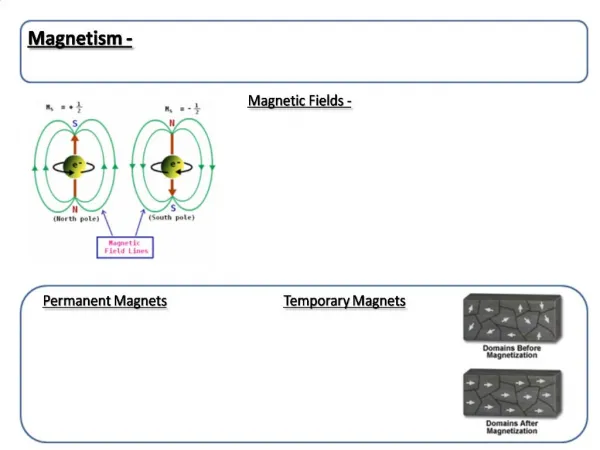
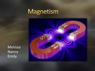
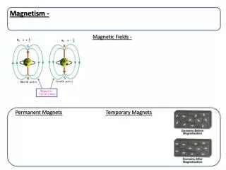
Magnetism. Magnetism: Permanent and Temporary 1. Assignments. 24/1-9,16-18,21-23, and 669/1-9 25/1-8,16,17,21. General Properties of Magnets. Like magnetic poles repel; unlike magnetic poles attract Magnetic field lines are directed from north to south

E N D
Magnetism Magnetism: Permanent and Temporary 1
Assignments • 24/1-9,16-18,21-23, and 669/1-9 • 25/1-8,16,17,21
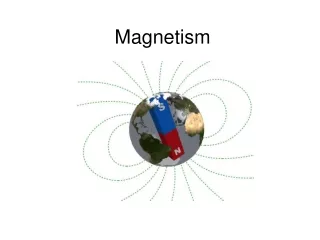
General Properties of Magnets • Like magnetic poles repel; unlike magnetic poles attract • Magnetic field lines are directed from north to south • Magnetic field lines always form close loops • A magnetic field exists around any wire that carries current
Gen’l Properties cont. • A coil of wire (SOLENOID) that carries a current has a magnetic field about a permanent magnet
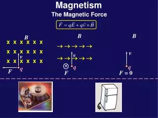
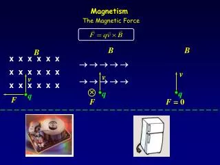
Forces Caused by Magnetic Fields • When a current-carrying wire is placed in a magnetic field, a force acts on the wire that is perpendicular to both the field and the wire. Meters operate on this principle. • Magnetic field strength is measured in tesla, T (one newton per ampere per meter). • B is the symbol for magnetic field
Forces cont. • An electric motor consists of a coil of wire (armature) placed in a magnetic field. When current flows in the coil, the coil rotates as a result of the force on the wire in the magnetic field. • The force a magnetic field exerts on a charged particle depends on the velocity and charge of the particle and the strength
Forces cont. • of the magnetic field. The direction of the force is perpendicular to both the field and particle’s velocity.
Key Equations • F = BIL Force on a current carrying wire in a magnetic field. Force = magnetic field strength x current x length of wire. Newton = tesla x amp x meter • F = BqV Force of a magnetic field on a single charged particle. Force = magnetic field strength x charge x velocity of the charge. Newton = tesla x coulomb x m/s
Hand Rule #1- B field direction around a current carrying wire • Point thumb in direction of current in the wire • Fingers of your hand circle the wire and show the direction of the magnetic field • Knuckles, N • Finger tips, S
Hand Rule #2 – Determine the polarity of an electromagnet • Wrap the fingers of your right hand around the loops in the direction of the current • Extended thumb points toward the N pole of the electromagnet
Sample Problems • A straight wire that carries a 5.0 amp current is in a uniform magnetic field oriented at right angles to the wire. When 0.10 m of the wire is in the field, the force on the wire is 0.20 n. What is the strength of the magnetic field, B?
Solution Known: Unknown: I = 5.0 amp B =? L = 0.10m F = 0.20 N F=BIL B = F/IL = 0.20N/5.0 amp(0.10m) = 0.40 T
Sample Problem A beam of electrons travels at 3.0 x 10⁶ m/s through a uniform magnetic field of 4.0 x 10⁻¹ T at right angles to the field. How strong is the force that acts on each electron? Known Unknown V = 3.0 x 10⁶ m/s F =? B = 4.0 x 10⁻¹ T Q = - 1.6 x 10⁻¹⁹ c
Solution F = BqV = 4.0 x 10⁻¹ T (-1.6 x 10⁻¹⁹c)(3.0 x 10⁶ m/s) = -1.9 x 10⁻¹³ Tcm/s = -1.9 x 10 -13 n
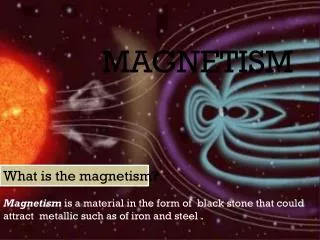
The small picture – how magnetism occurs • Domain theory – when enough atoms of a substance line up in the same direction • Strong magnets – iron and steel • Very strong – Alnico alloy • Weak – aluminum, platinum • Natural – magnetite or lodestodes formed when rock was molten
Magnetic field lines Magnetic flux, (F) – number of field lines passing through a surface Unit: weber = 1 nm/amp Magnetic flux density, B = F /A Unit: wb/m2 = nm/a m2 = n/am 1 wb/m2 = 1 Tesla Earth, 10–4 T Humans, 10–11 T
Electromagnetism-flowing electrical current magnetism Ampere’s Rule for parallel, straight conductors: F = 2k L I1 I2 / d K = 10 –7 n/a2 = 10 –7 Tm/a L, length, m I, current, a d, distance between wires
Solenoid – conducting linear coil which acts like a bar magnet Increase B, magnetic flux density by Increasing the current Adding loops of wire Inserting an iron core into solenoid – now it is an electromagnet
Michael Faraday and Joseph Henry around the same time… • Discovered that when there is relative motion between a magnetic field and a complete circuit (and the conductor cuts across the magnetic field), that electricity will flow!!!
Hand rule #3 – shows force acting on wire in B field • Lay right hand flat, palm up • Extend thumb 90 degrees to rest of fingers • Fingers point in direction of B field • Thumb points in direction of current, I • Imaginary vector coming up perpendicular out of the palm points in the direction of force acting on current carrying wire.
If current flows, there must be an EMF – this is EM induction Faraday’s Law of Induction: E = - N DF / D t E, emf, volts -N, # of turns of wire (- means the current opposes the change that induced it) DF, change in flux in weber, wb D t, change in time, sec
Sample Problem • If a coil of 200 turns is moved perpendicularly in a magntic field at a constant rate, find the induced emf. The flux linkage change ( DF / D t) is 4.00 x 10⁻⁶ wb in 0.0100 sec.
Problem solution E = - N DF / D t E = (-200)(4.00 x 10 –6 wb) 1.00 x 10 –2 s E = -8.00 x 10 –2 v Imagine what thousands of turns would produce!
Electric Generators • Convert mechanical energy into electrical energy by rotating a looped conductor (armature) in a magnetic field • Alternating-Current electricity produced is conducted by slip rings and brushes to be used * • Direct current can be produced by using split rings *
A coil with a wire is wound around a 2.0 m2 hollow tube 35 times. A uniform magnetic field is applied perpendicular to the plane of the coil. If the field changes uniformly from 0.00 T to 0.55 T in 0.85 s, what is the induced emf in the coil?
A = 2.0 m2 N = 35 B = .55 T T = 0.85 s E = -N D F / D t = - NBA / D t E = 35 (0.55 T) (2 m 2) 0.85s E = 45.3 v http://www.phys.ufl.edu/~phy3054/extras/contents/Welcome.html
Lenz’s Law - • The direction of an induced current is such that the magnetic field resulting from the induced current opposes the change in the field that caused the induced current. • When the N pole of a magnet is moved toward the left end of a coil, that end of the coil must become a N, causing induced current flow in opposition.
Lenz's law: The induced emf generates a current that sets up a magnetic field which acts to oppose the change in magnetic flux.
Another way of stating Lenz's law is to say that coils and loops like to maintain the status quo (i.e., they don't like change). If a coil has zero magnetic flux, when a magnet is brought close then, while the flux is changing, the coil will set up its own magnetic field that points opposite to the field from the magnet.
On the other hand, a coil with a particular flux from an external magnetic field will set up its own magnetic field in an attempt to maintain the flux at a constant level if the external field (and therefore flux) is changed.
Inductance • The property of an electric circuit by which a varying current induces a back emf in that circuit or a neighboring circuit. • Mutual Inductance, M • Self Inductance, L
Mutual Inductance • Effect that occurs in a transformer when a varying magnetic field created in the primary coil is carried through the iron core to the secondary coil, where the varying field induces a varying emf.
M = -Es / D Ip/ D t Shows the ratio of induced emf in one circuit to the rate of change of current in the other circuit. M, inductance, Henry Es, average induced emf across secondary D Ip/ D t, time rate of change in current in primary coil - sign, induced v opposes D I
Problem • Find the mutual inductance in an electrical device in which the EMF in the secondary is 200. V and the rate of change of the current is 2.0 x 10⁻³ a/s. • M = -Es / D Ip/ D t • M = -200v / 2.0x10⁻³a/s • M = -1x10⁵ H
Self Inductance Ratio of induced emf across a coil to the rate of change of current in the coil L = -E / D I / D t L, henry I, current, amp T, time, sec
Effective Value • www.sfu.ca/.../Graphics/Root_Mean_Square.gif Ieff = 0.707 Imax Veff = 0.707 Vmax
Transformer • Two separate coils of wire placed near one another that are used to increase or decrease AC voltages with little loss of energy. • It contains a Primary coil and a Secondary coil • When the primary is connected to AC voltage, the changing current creates a varying magnetic field that is carried through the core to the secondary coil.
Transformer, cont. In the secondary coil, the varying field induces a varying emf. This is called mutual inductance Secondary voltage = secondary #turns Primary voltage primary # turns Power = Voltage x Current
Transformers lose no power • Pp = Ps VpIp = VsIs • Transformer Equation: • Is = Vp = Np • Ip Vs Ns
Transformer Problem • A step-up transformer has a primary coil consisting of 200 turns and a secondary coil that has 3000 turns. The primary coil is supplied with an effective AC voltage of 90.0v. A)What is the Vs? B)If Is = 2.00a, find Ip. C) What is the power in the primary circuit?
Solution to Transformer Problem • Vs = NsVp/Np = 3000(90.0V)/200 = 1.35 kV • Pp = Ps, VpIp = VsIs Ip = VsIs/Vp = • Ip =1350v(2.00a)/90.0v = 30.0a • Pp = VpIp = 90.0v(30.0a) = 2.70 kW