Download
1 / 159
1.65k likes | 1.88k Views
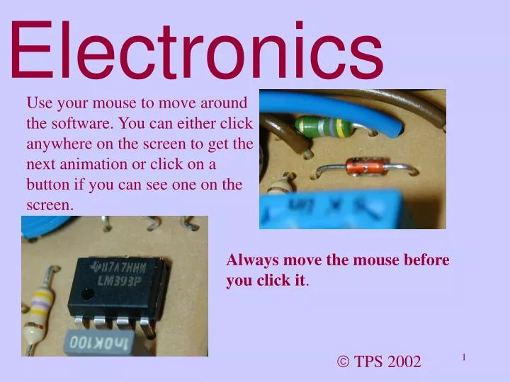
Electronics. Use your mouse to move around the software. You can either click anywhere on the screen to get the next animation or click on a button if you can see one on the screen. Always move the mouse before you click it. TPS 2002. Electronics. Introduction Ohm’s Law

E N D
Electronics Use your mouse to move around the software. You can either click anywhere on the screen to get the next animation or click on a button if you can see one on the screen. Always move the mouse before you click it. TPS 2002
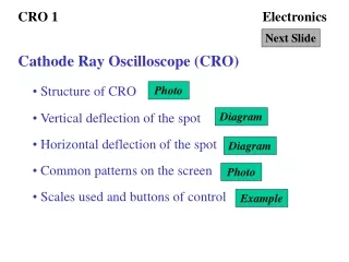
Electronics Introduction Ohm’s Law Power Calculations Resistors in Series and Parallel Capacitors Alternating Current Waveforms The Potential Divider Transistor Circuits Questions
Introduction Basic Concepts Simple Circuits Questions Main Menu
Basic Concepts Return previous slide Electric current is due to the flow of charge. In a solid conductor, the charge is carried by electrons. In a solid conductor, an electric current is due to the flow of electrons.
Basic Concepts Return previous slide • Conductors include: • copper • gold • silver • lead All metals And water (not distilled) which is why you should not use mains appliances in the presence of water.
Basic Concepts Return previous slide • Insulators include: • Rubber • Plastic • Most solid non metals • Glass Glass, unless it is very hot, is one of the best insulators available.
Basic Concepts Return previous slide Electric current (I) is measured in ampere (A) - I is the symbol used to indicate current. The “amp” is a rather large unit for most electronic applications so we use the following sub-multiples: 1 mA = 0.001A that is 1 / 1 000 th of an ampere You already know that 1mm is 1/1000th of an metre so there is nothing new here. 1 A = 0.000 001A that is 1 / 1 000 000 th of an ampere
Basic Concepts Return previous slide Voltage is measured in volt (V) Common sub-multiples of the volt (less than a volt) include: 1 mV = 0.001V that is 1 / 1 000 th of a volt 1 V = 0.000 001V that is 1 / 1 000 000 th of a volt Common multiples of the volt (greater than a volt) include: 1 kV = 1 000 V 1 MV = 1 000 000 V The kV and the MV are not common in electronics.
Basic Concepts Return previous slide Resistance is measured in ohm () Common sub-multiples of the ohm (less than an ohm) include: 1 m = 0.001 that is 1 / 1 000 th of an ohm 1 = 0.000 001 that is 1 / 1 000 000 th of an ohm This is pronounced micro ohm Common multiples of the ohm (greater than an ohm) include: 1 k = 1 000 1 M = 1 000 000 The m and the are not common in electronics.
Basic Concepts Return previous slide Capacitance is measured in farad (F) Common sub-multiples of the farad (less than a farad) include: 1 m F = 0.001 F that is 1 / 1 000 th of a farad 1 F = 0.000 001 F that is 1 / 1 000 000 th of a farad 1 n F = 0.000 000 001 F that is 1 / 1 000 000 000 th of a farad this is written in full as a nano farad 1 p F = 0.000 000 000 001 F that is 1 / 1 000 000 000 000 th of a farad This is written in full as pico farad
Basic Concepts Return previous slide Here is a summary of many of the available multiples and sub-multiples Symbol Prefix Multiplication factor T tera 1012 1 000 000 000 000 G giga 109 1 000 000 000 M mega 106 1 000 000 k kilo 103 1 000 h hecto 102 100 da deca 101 10 d deci 10-1 0.1 c centi 10-2 0.01 m milli 10-3 0.001 micro 10-6 0.000 001 n nano 10-9 0.000 000 001 p pico 10-12 0.000 000 000 001 f femto 10-15 0.000 000 000 000 001 a atto 10-18 0.000 000 000 000 000 001 The most frequently used are in bold.
Basic Concepts Return previous slide Resistors are marked with a series of coloured rings to give us an idea of how big their resistance is. This gold band indicates that the tolerance of the resistor is ±5% (plus or minus 5 percent). This means that its resistance is between 3 400 and 3 800 . We say it is nominally3 600 . The third band is red. This means that there are 2 zeros. The second band is blue. This means the second digit is 6. The first band is orange. This means the first digit is 3. So the resistor is nominally 3 600 .or 3k6
Basic Concepts Return previous slide The colours used for the first three bands and their meanings are as follows: Colour Number Number of zeros Black 0 none Brown 1 0 Red 2 00 Orange 3 000 Yellow 4 0 000 Green 5 00 000 Blue 6 000 000 Violet 7 0 000 000 Grey 8 00 000 000 White 9 000 000 000
Basic Concepts Return previous slide The colours used for the last band and their meanings are as follows: Gold ± 5 % Silver ± 10 % No band ± 20 % Resistors are manufactured in “preferred values”. That means that you can only buy certain values. The preferred values for resistors with a tolerance of ±20% are: 10,15,22,33,47,68 and 100. These are just the first two significant figures. You can buy a 1500 but not a 2000 .
Basic Concepts Return previous slide The preferred values for 10% resistors are: 10 12 15 18 22 27 33 39 47 56 58 82 100 &
Basic Concepts Return previous slide The preferred values for 5% resistors are: 10 11 12 13 15 16 18 20 22 24 27 30 33 36 39 43 47 51 56 62 68 75 82 91 100 &
Basic Concepts Home Return previous slide In summary: Voltage is measured in Current is measured in Resistance is measured in Capacitance is measured in Volt (V) Ampere (A) ohm () farad (F) 3MV = 3 000 000 V 2kV = 2 000 V 5mV = 0.005 A 7A = 0.000 007 A & 1nF = 0.000 000 001 F 1pF = 0.000 000 000 001 F
Input Processor Output Return to menu slide Simple Circuits Simple circuits have three main blocks of components in common that perform the same type of job. These are: • This is called a block diagram. • The processor is the decision-making part of the system. • The input is a sensor that transforms everyday phenomena such as temperature and heat to an electric signal that the processor can deal with. • The output is a device that converts an electric signal from the processor into something that we want.
Input Processor Output Simple Circuits Simple circuits have three main blocks of components in common that perform the same type of job. These are: Examples of input devices include: Pressure pads LDRs Thermistors Reed switches Return to previous slide
Input Processor Output Simple Circuits Simple circuits have three main blocks of components in common that perform the same type of job. These are: Examples of output devices include: Lamps LEDs Motors Solenoids Return to previous slide
Input Processor Output Simple Circuits Simple circuits have three main blocks of components in common that perform the same type of job. These are: Examples of basic processors include: Transistors Operational amplifiers Return to previous slide
Home Input LDR Processor Processor Output Lamp Simple Circuits Simple circuits have three main blocks of components in common that perform the same type of job. These are: What would the block diagram look like for a system that brought on a light when it got dark? Return to previous slide
Questions - Simple Circuits Return to menu slide 1 Write down the units of voltage, capacitance, resistance and current. What is the symbol for current? 2 Write out 22mA and 420 pF in full. 3 Give three examples of input devices. 4 Write out a block circuit diagram for a device that could lift up a trap door when a beam of light was broken. 5 What is the nominal value and tolerance of this resistor? 6 What would the colours of a 47M resistor be? ANSWER ANSWER ANSWER ANSWER ANSWER ANSWER
Solutions - Simple Circuits Return 1 Write down the units of voltage, capacitance, resistance and current. What is the symbol for current? Voltage volt (V) Capacitance farad (F) Resistance ohm () Current ampere (A) The symbol for current is I
Solutions - Simple Circuits Return 2 Write out 22mA and 420 pF in full. 22mA = 22 x 0.001 A = 0 . 22 A 420 pF = 420 x 0.000 000 000 001 F = 0 . 000 000 000 42 F
Solutions - Simple Circuits Return 3 Give three examples of input devices. • Pressure pads • LDRs • Thermistors • Reed switches
Solutions - Simple Circuits LDR LDR Processor Processor Motor Solenoid Return 4 Write out a block circuit diagram for a device that could lift up a trap door when a beam of light was broken. or Note that a bulb is not an input device as it gives out light.
Solutions - Simple Circuits Return 5 What is the nominal value and tolerance of this resistor? This gold band indicates that the tolerance of the resistor is ±5% (plus or minus 5 percent). The third band is red. This means that there are 2 zeros. The second band is black. This means the second digit is 0. The first band is brown. This means the first digit is 1. So the resistor is nominally 1 200 .
Solutions - Simple Circuits Return 6 What would the colours of a 47M resistor be? The resistor is nominally 47 000 000 . This gold band indicates that the tolerance of the resistor is ±5% (plus or minus 5 percent). The third band is blue. This means that there are 6 zeros. The second band is violet. This means the second digit is 7. The first band is yellow. This means the first digit is 4.
Ohm’s Law Return to menu slide Ohm’s Law states that so long as the physical conditions remain constant, the current through a conductor is proportional to the voltage across it. This gives us the formula: Voltage = current x resistance V = I R We can rearrange this equation to give either R = V / I or I = V / R
Ohm’s Law Low resistance Current High resistance Voltage Return previous slide What does it mean? “Physical conditions remaining constant” - This really means as long as the temperature remains constant. Usually it does. “The current through a conductor is proportional to the voltage across it” - this means that if you double the voltage, you get twice the current. Triple the voltage and you triple the current etc.
Ohm’s Law Return previous slide Calculations using Ohm’s law fall into three types: What is the resistance if ? What is the current if ? What is the voltage if ? (Use R = V / I) (Use I = V / R) (Use V = I x R) E.G. What resistance could you use with a 10V supply to limit the current to 15mA? E.G. A 430 resistor protects an LED in a 5V circuit. What is the current through the LED? E.G. 12mA runs through a prorctive resistor of resistance 820 . What is the voltage across the resistor ? R = V / I = 10 / 0.015 I = V / R = 5 / 430 V = IR = 0.012x820 667 so use 680 = 12 mA = 9.84 V
Ohm’s Law Return previous slide 0.7 V Diode The voltage across the diode is 0.7 V and the cell produces 1.5 V. What is the current through the resistor? 820 1.5V If you can’t see how to do it straight away, write the values given onto the diagram. Voltage across the resistor = 1.5V (provided by the cell) - 0.7V (lost across the diode) = 0.8V Using I = V / R = 0.8 / 820 = 1mA
Ohm’s Law - Questions Home Return previous slide 1 A power supply drives a current of 500mA through a bulb with a working resistance of 3. What voltage is the power supply? 2 A power supply provides 12 V to a bulb passing 3 A. What is the working resistance of the bulb? 3 A 47 k resistor has a pd of 9 V across it. What current passes through the resistor? 4 An 18V power supply is placed across a resistor of resistance 10k. What current will flow through the resistor? 5 The effective resistance of a small motor is 5 . What current passes through it if a cell of voltage 6 V is placed across it? Solution 1 Solution 2 Solution 3 Solution 4 Solution 5
Ohm’s Law - Solutions Return 1 A power supply drives a current of 500mA through a bulb with a working resistance of 3. What voltage is the power supply? V = I x R so V = 0.5 x 3 =1.5 volt
Ohm’s Law - Solutions Return 2 A power supply provides 12 V to a bulb passing 3 A. What is the working resistance of the bulb? V = I x R So R = V / I = 12 / 3 = 4 A
Ohm’s Law - Solutions Return 3 A 47 k resistor has a pd of 9 V across it. What current passes through the resistor? V = I x R So I = V / R = 9 / 47 000 = 0.000 191 A = 191 A
Ohm’s Law - Solutions Return 4 An 18V power supply is placed across a resistor of resistance 10k. What current will flow through the resistor? V = I x R so I = V / R = 18 / 10 000 = 0.001 8 A = 1.8 mA
Ohm’s Law - Solutions Return 5 The effective resistance of a small motor is 5 . What current passes through it if a cell of voltage 6 V is placed across it? V = I x R So I = V / R = 6 / 5 = 1.2 A
Return main menu Power Calculations The detail from the bottom of an electrical appliance shown here gives a very useful, commonly used method of writing the power of the appliance. 20 VA is exactly the same as 20 W (20 watts). The more powerful an appliance is, the greater the number will be. An electric fire might well be 2 or 3 kW (2 000 or 3 000 W). 1W is sometimes called 1VA because you can calculate the power by multiplying “the volts by the amps”! Power = current x voltage or P = I V
Return previous slide Power Calculations Remember that : 20VA means a power of 20W and that P = I x V This device runs from a 230V mains supply. What can we learn from this information? Well, we know that P = IV; we also know the voltage and the power, so we can calculate the current I. I = P / V So I = 20 / 230 = 87 mA
Return previous slide Power Calculations Can you match these typical power ratings with the device that they describe? 60 W 500 mw Light emitting diode 100 mW Power station Torch Bulb 20 W 60 MW Electric lamp Halogen desk lamp
Return previous slide Power Calculations 100 mW 60 MW Power station Light emitting diode 500 mW Torch Bulb 20 W Electric lamp Halogen desk lamp 60 W
Return previous slide Power Calculations - the formulae Power = current x voltage P = IV so I = P / V and V = P / I But from Ohm’s Law, V = I x R So P = I x IR P = I2R And from Ohm’s Law, I = V / R So P = (V/R) x V P = V2/R
Return previous slide Home Power Calculations - Questions 1 A diode has a voltage of 0.7V across it and a current of 100mA flowing through it. What is the power dissipated in the diode? 2 A wire carries a current of 5 mA and the power dissipated in the wire is 2.5 W. What is the voltage across the wire? 3 What is the current passing through a coil that dissipates 40mW when a voltage of 5V is applied across it? 4 A current of 10 mA passes through a 10 resistor. What is the power dissipated in the resistor? 5 A voltage of 9 V is applied across a 10 k resistor. What power is dissipated in the resistor? Answer 1 Answer 5 Answer 3 Answer 4 Answer 2
Power Calculations - Solutions 1 A diode has a voltage of 0.7V across it and a current of 100mA flowing through it. What is the power dissipated in the diode? P = IV so P = 0.1 x 0.7 = 0.07 = 70 mW
Power Calculations - Solutions 2 A wire carries a current of 5 mA and the power dissipated in the wire is 2.5 W. What is the voltage across the wire? P = IV So V = P / I = 0.000 0025 / 0.005 = 0.000 5 W = 0.5 mW = 500 W
Power Calculations - Solutions 3 What is the current passing through a coil that dissipates 40mW when a voltage of 5V is applied across it? P = IV So I = P / V = 0.04 / 5 = 0.008 W = 8mW
Power Calculations - Solutions 4 A current of 10 mA passes through a 10 resistor. What is the power dissipated in the resistor? P = I2R = 0.012 x 10 = 0.001 =1mW
Power Calculations - Solutions 5 A voltage of 9 V is applied across a 10 k resistor. What power is dissipated in the resistor? P =V2/R = 92 / 10 000 0.0081 = 8.1 mW