Download

1 / 36
360 likes | 665 Views
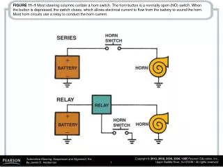
FIGURE 28–1 Most steering columns contain a horn switch. The horn button is a normally open (NO) switch. When the button is depressed, the switch closes, which allows electrical current to flow from the battery to sound the horn. Most horn circuits use a relay to conduct the horn current.

E N D
FIGURE 28–1 Most steering columns contain a horn switch. The horn button is a normally open (NO) switch. When the button is depressed, the switch closes, which allows electrical current to flow from the battery to sound the horn. Most horn circuits use a relay to conduct the horn current.
FIGURE 28–2 The airbag inflates at the same time the driver moves toward the steering wheel during a front-end collision and supplements the protection of the safety belt.
FIGURE 28–3 The airbag module attaches to the steering wheel and is removed as an assembly to service the steering wheel and column.
FIGURE 28–4 The steering shaft links the steering wheel to the steering gear while the column jacket, which surrounds part of the shaft, holds support brackets and switches. This steering shaft has a small intermediate section between the main section and the steering gear.
FIGURE 28–5 A pot joint is a flexible coupling used to join two shafts that allow plunging motion.
FIGURE 28–6 A typical intermediate steering shaft assembly showing a U-joint and related components.
FIGURE 28–7 A flexible coupling is used to isolate road noise and vibration from the steering shaft.
FIGURE 28–8 Steering column covers are often part of the interior trim.
FIGURE 28–9 Collapsible steering columns include a mesh design that crushes easily, a bearing design that allows one section of the column to slide into the other, and a breakaway device that separates the steering column from the body of the vehicle in the event of a front-end collision.
FIGURE 28–10 Tilt mechanisms vary by design and vehicle manufacturer, although most use a ratchet to position the top portion of the steering column.
FIGURE 28–11 Typical steering column showing all of the components from the steering wheel to the steering gear.
FIGURE 28–12 The steering shaft splines onto the steering wheel.
FIGURE 28–13 The toe plate seals the hole from the steering shaft and helps seal out noise and moisture.
FIGURE 28–14 The upper section of the steering column includes the lock housing and switches.
FIGURE 28–15 The upper section of the steering column contains the steering shaft bearing.
FIGURE 28–16 The lock plate engages an ignition lock pawl to keep the steering wheel in one position when the ignition is off.
FIGURE 28–17 As the steering wheel is turned, the nut moves up or down on the threads, shown using a bolt to represent the worm gear and the nut representing the gear nut that meshes with the teeth of the sector gear.
FIGURE 28–18 Steering gear ratio is the ratio between the number of degrees the steering wheel is rotated to the number of degrees the front wheel turns.
FIGURE 28–19 Constant-ratio steering gear sector shaft. Notice that all three gear teeth are the same size.
FIGURE 28–20 Variable-ratio steering gear sector shaft. Notice the larger center gear tooth.
FIGURE 28–21 The sector gear meshes with the gear teeth on the ball nut.
FIGURE 28–22 A typical manual recirculating ball steering gear.
FIGURE 28–23 The sector shaft is supported by bushings, one in the housing and one in the side cover.
FIGURE 28–24 Worm bearing preload is a turning force measured in in.-lb or N-M, and worm endplay is axial movement measured in fractions of an inch or millimeters.
FIGURE 28–25 The first step to adjust worm gear freeplay is to bottom the worm gear nut, using a spanner wrench designed to fit into the two holes in the nut.
FIGURE 28–26 After the worm gear nut has been tightened, measure 1/2 inch (13 mm) and mark the case. Using the spanner wrench, rotate the worm gear nut counterclockwise 1/2 inch, align the marks, and then tighten the retaining the nut. This procedure gives the proper worm gear endplay.
FIGURE 28–27 Performing an overcenter adjustment requires the use of a beam-type inch-lb torque wrench. After the worm bearing preload procedure has been completed, use the torque wrench to measure the rotating torque, which should be 6 to 15 lb-in. If the rotating torque is within the specified range, adjust the overcenter adjustment screw until you achieve 6 to 10 lb-in. more rotating torque and then tighten the retaining nut.
FIGURE 28–28 Sector shaft endplay is the measurement of how far the sector shaft can move axially and is measured in fractions of an inch or millimeters.
FIGURE 28–29 Rack-and-pinion steering gear operation is simple, direct, and the rack is in a straight line to the front wheels.
FIGURE 28–30 A typical manual rack-and-pinion steering gear used in a small front-wheel-drive vehicle.
FIGURE 28–31 The spring-loaded rack support positions the rack to keep it from rubbing against the housing and establishes the pinion torque.
FIGURE 28–32 To adjust the rack-and-pinion gear preload, loosen the retaining nut and tighten the adjuster nut until it bottoms. Then loosen 60 degrees (one “flat” of the six-sided retainer). Tighten retaining nut.
FIGURE 28–33 A small air tube is used to transfer air between the boots as they extend and compress during turns.
FIGURE 28–34 This manual rack-and-pinion steering gear mounts to the bulkhead (firewall), whereas others mount to the engine cradle or frame of the vehicle.
FIGURE 28–35 Pinion torque is a turning torque force measured in inch-pounds or Newton-meters. Tightening the rack support against the rack increases the pinion torque.
FIGURE 28–36 Pinion bearing preload is a measurement of the turning force required to overcome the resistance of the pinion shaft bearings.