ELECTRONIC SWITCH CONTROL THROUGH RF(RADIO FREQUENCY)
90 likes | 200 Views
Create RF remote control to operate home appliances like fan, lights. Use HT12E, HT12D encoders/decoders. Simple assembly with push-to-on switch, relay, LED. Operate via single remote transmitter unit. Implement secure 433MHz ASK communication.

ELECTRONIC SWITCH CONTROL THROUGH RF(RADIO FREQUENCY)
E N D
Presentation Transcript
ELECTRONIC SWITCH CONTROL THROUGH RF(RADIO FREQUENCY) GROUP MEMBERS: Anil Kumar LoyaME12B1002 RITESH KUMARCE12B1019 SAHIL TAMBOLIME12B1037 VARALA RAJATH ME12B1038
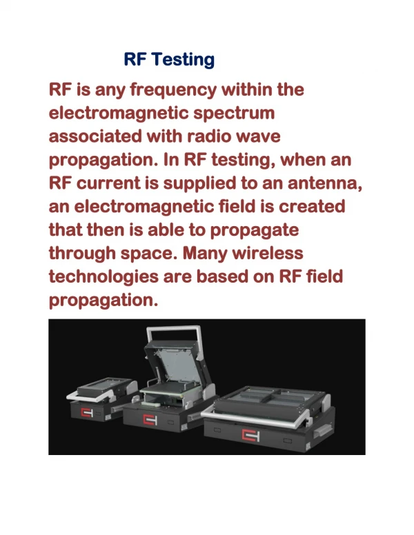
INTRODUCTION • This is a simple type remote control by using RF communication without microcontroller. In this project a remote has been designed for various home appliances like fan, lights, etc. It gives lot of comfort to the user since we can operate it by staying at one place. We can control any of the appliances by using this remote. In this project consist of two sections, transmitter (remote) and receiver section. Whenever we are pressing any key in the remote it generates the corresponding RF signals, and these signals are received by the receiver unit. ASK transmitter and receiver is used as transmitter and receiver. HT12E, HT12D encoders and decoders are used in this electronic circuit.
COMPONENTS USED: • IC HT12D,HT12E,LM7805. • TRANSISTOR BC558,SL100. • ASK TRANSMITTER 433MHZ. • ASK RECEIVER 433MHZ. • PUSH TO ON SWITCH. • RELAY SWITCH. • LED (RED). • RESISTORS. • CAPACITORS.
REMOTE SECTION • In remote section consist of an encoder (HT 12E) and a ASK transmitter. The encoder generates 8 bit address and 4bit data. Whenever we press any key in the remote the encoder generates corresponding 4bit data and send this data by using ASK transmitter. The transmitting frequency is 433MHz. The transmitter output is up to 8mW at 433.92MHz. RECEIVER SECTION • At the receiver section ASK receiver is present. The receiver also operates at 433 MHZ. It receives the datas from the transmitter. Then the decoder (HT12D) decodes the data and it will enable the corresponding output pin. Each output pins are connected to separate flip flops. The output of encoder will change the state of flip flop. This output is not cable to drive a relay directly. So we use current driver (transistor SL100). The appliance is connected to 230v AC through the relay and appliance will start. The relay will be re-energized when the same switch is pressed in the remote and the state of flip flop is changed and appliance will switch-off.
IC HT12E: HT12E is an encoder integrated circuit of 2^12 series of encoders. They are paired with 2^12 series of decoders for use in remote control system applications. It is mainly used in interfacing RF and infrared circuits. The chosen pair of encoder/decoder should have same number of addresses and data format. Pin Diagram
IC HT12D: HT12D is a decoder integrated circuit that belongs to 212 series of decoders. This series of decoders are mainly used for remote control system applications, like burglar alarm, car door controller, security system etc. It is mainly provided to interface RF and infrared circuits. They are paired with 212 series of encoders. The chosen pair of encoder/decoder should have same number of addresses and data format. Pin Diagram
REFERENCES: • WWW.CIRCUITSTODAY.COM • WWW.WIKIPEDIA.COM THANK YOU