Download
1 / 14
140 likes | 282 Views
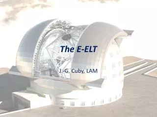
Pre-focal wave front correction and field stabilization for the E-ELT. L. Jochum, N. Hubin, E. Vernet, P.-Y. Madec, M. Dimmler, M. Mueller, B.Sedghi. Outline. E-ELT optics layout E-ELT AO components Main axes control Field Stabilization Unit Adaptive Unit Conclusions. E-ELT Optics Layout.

E N D
Pre-focal wave front correction and field stabilization for the E-ELT L. Jochum, N. Hubin, E. Vernet, P.-Y. Madec, M. Dimmler, M. Mueller, B.Sedghi
Outline • E-ELT optics layout • E-ELT AO components • Main axes control • Field Stabilization Unit • Adaptive Unit • Conclusions
E-ELT Optics Layout 5 mirror adaptive telescope
E-ELT AO components • Disturbers • Atmospheric turbulence • Windload • Gravity and thermal effects • Task for E-ELT pre-focal AO • real time wave front correction for theE-ELT focal plane, reaching diffractionlimit of the telescope in the NIR • Correction devices • Telescope main axes control • Field stabilization mirror • Adaptive mirror • Wave front sensing systems • NGS, LGS, laser sources, beam transport and launch, WFS, RTC
Main axes control Residual of main axes control input disturbance for image stabilization
M5 – Field Stabilization Unit • Task: Tip tilt correction forimage stabilization • Components: • Mirror • Field stabilization system • Mounting structure • Control system • Auxiliary Equipment • Incoming disturbance: • 1” rms residual tip tilt • Dominated by wind shaking • Conservative assumptions: • 10m/s wind speed @ 10 m • No dome • 30% safety margin
M5 correction • Required output • Residual on sky tip-tilt: • < 0.07” rms (goal 0.06”) over the entire frequency range • < 0.004” rms for [9Hz to ] all peaks < 2σ Conditions: WFS sampling: 100Hz RON no noise WFS delay 10 ms RTC delay 1 ms Phase margin >45 deg Modulus margin >0.6 • Communication with RTC[25 - 1200]Hz E-ELT control simulation:main axes + M5 Remaining wave front correction adaptive mirror with positioning system
M4 – Adaptive Unit • Components: Adaptive mirror, Positioning system,Mounting structure, Control system, Auxiliary Equipment • Tasks: correction of… • …small amplitude residual tip-tilt • …high order wavefront (real-time) • Atmosphere • wind shake • low spatial frequency telescope errors • …large amplitude low frequency tip-tilt • …lateral pupil position • Telescope gravity • Thermal load • adapter tracking wobble & run-out errors • Nasmyth foci selection Adaptive mirror Positioning system (4 DoF)
Adaptive mirror main requirements • Fitting error: 145 nm rms (goal 110) • Temporal error: 60 nm rms (goal 43) • Tip-tilt after M4: 1.3 mas @ 1 kHz WFS sampling • Total stroke defined for worst seeing conditions (2.5arcsec seeing, 100 m outer scale) • Optical quality, mass, power consumption, dynamic behavior, passive stability (lookup tables), environment, …. • High reliability (key element for E ELT) under median seeing conditions
Required tip-tilt correction after M4 • Incomming disturbance:0.119” residual on sky rmsafter telescope & M5 correction • Conservative assumptions: • 10m/s wind speed @ 10 m • Exponential wind profile • No dome • 30% safety margin in original data E-ELT control simulation:main axes + M5 + M4
3 step disturbance correction Telescope main axes control Remaining tip tilt < 1” rms M5 Low frequency, high stroke M4 High frequency, low stroke 1.3 mas residual rms error compatible with diffraction limit in NIR
Conclusions • E-ELT will be an adaptive telescope, NIR diffraction limited • In-built Field stabilization mirror • In-built adaptive mirror • Demanding requirements pushing state of the art technology • Feasibility studies, conceptual and preliminary design, breadboarding and prototyping of critical components carried out by industry under ESO contracts • 16h00 Armando Riccardi, 16h40 : Daniele Gallieni E-ELT M4AU development at Microgate • 16h20 Bruno Crépy, 17h20 Jean-Christophe Sinquin E-ELT M4AU development at CILAS • 17h40 Javier Barriga E-ELT M5FU development at NTE