Download

1 / 51
620 likes | 920 Views
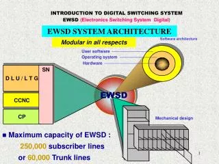
Digital Switching. Kashif Jadoon. Contents. Network Systems Network Trends Switch Fabric Type of Switches Optical Cross Connects Optical Cross Connects Architecture Large Scale Switches Optical Router Applications. Development Milestones. 2004 International Engineering Consortium.

E N D
Digital Switching KashifJadoon
Contents • Network Systems • Network Trends • Switch Fabric • Type of Switches • Optical Cross Connects • Optical Cross Connects Architecture • Large Scale Switches • Optical Router • Applications
Development Milestones 2004 International Engineering Consortium
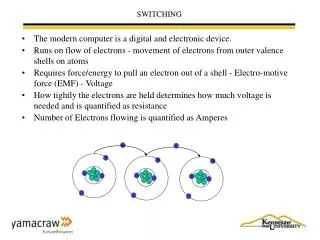
Network • Network Connectivity • Point to Point: one to one • Broadcast: one to many • Multicast: many to many • Network Span • Local / Metro Area Network • Wide Area Network • Long Haul Network • Data Rates • Voice 64kbps • Video 155Mbps, etc. • Service Types • Constant or Variable bit rate • Messaging • Quality of Service
Ports Ports Fully Connected, Un-switched Network Problem • limited and could not scale to thousands or millions of users Solution - switched network
Switched Network Pervasive, high-bandwidth, reliable, transparent
Optical Network - Issues • Capacity 2.5 Gb/s 10 Gb/s 40 Gb/s Larger • Control (switching) • Electronics • 10 Gb/s (GaAs, InP) can deliver low order optical cross connects (16 x 16) • > 10 Gb/s ??(mainly power dissipation) • Optical • Reconfiguration: • Static or dynamic
Optical Network Elements • Dense Wavelength Division Multiplexing • Optical Add/Drop Multiplexers (OADM) • Optical Gateways: • A critical network element. • A common transport structure to cater for • variety of bit rates and signal formats, ranging from asynchronous legacy networks to 10–Gbps SONET systems, • a mix of standard SONET and ATM services.
Switching - Electrical Right now, the optical switches have electrical core, where • Light pulses are converted back into electrical signals so that their route across the middle of the switch can be handled by conventional ASICs (application specific integrated circuits). • This has a number of advantages: • Enabling the switches to handle smaller bandwidths than whole wavelengths, which fits in with current market requirements. • Easier network management, because standards are in place and products are available. Optical equivalents are not, at present. • But, there are concerns that electrical cores won’t be able to cope with the explosion in the number of wavelengths in telecom networks (deployment of DWDM). • Until recently, state-of-the-art ASIC technology wouldn’t support anything more than a 512-by-512-port electrical core, and carriers demanding for at least double this capacity.
Optical Network Elements - Switches • Optical Bidirectional Line Switched Rings • Optical Cross-Connect (OXC) • Efficient use of existing optical fibre facilities at the optical level becomes critical as service providers started moving wavelengths around the glob. Routing and grooming are key areas, and that is where OXCs are used. International Engineering Consortium, 2004
Optical Switches • To provide high switching speed • To avoid the electronics speed bottleneck • I/O interface and switching fabric in optics • Switching control and switching fabric in optics • Switches act as routers and redirect the optical • signals in a specific direction. • It uses a simple 2x2 switch as a building block Main feature: Switching time (msecs - to- sub nsecs)
All Optical Switches • That’s the theory. But, things are turning out a little different in practice. • Vendors are finding ways of building larger scale electrical cores, with switch of many thousands of ports. • This may encourage carriers to put off decisions on moving to all-optical switches. • Does this mean that is the end of the idea of all-optical networks? • Well, not really. All that it might do is delay things.
Optical • Electrical Limits • High power consumption: e.g. 1024x1024: 4 kW • Jitter: very large • Large switches • Need OE/EO conversion • Bipolar or GaAs 1024 512 256 128 Number of ports 64 32 16 Electrical 8 10 MHz 100 MHz 1 GHz 10 GHz 100 GHz Data rate DS3 OC3 OC12 OC48 OC192 Electrical vs. Optical - Cross Connects M C Wu
Switching: Types • Circuit Switching: E.g. Telephone • Continuous streams • no bursts • no buffers • Connections are created and removed • Buffering does not exist in circuit-switches • Packet Switching: Uses store & forward • The configuration may change per packet • Switching/forwarding is based on the destination address mapping • Switching table is used to provide the mapping • Switching table changes according to network dynamics (e.g. congestion, failure)
Electrical control Electrical control Optical input Optical output Optical input Optical output Switching Fabric • Electro-optical 2 x 2 switching elements are the key devices in the fabrication of N x N optical data path. • The switching elements rely on the electro-optic effect (i.e., the application of an electric field to an electro-optical material changes the refractive index of the material). • The result is a 2x2 optical switching element whose state is determined by an electrical control signal.
Input interface Output interface Switching fabric Switching control Switching Fabric – contd.
... ... 1.3 mm intra-office Transponders ... ... Optical Crossconnect (OXC) ... ... Optical transport system (1.55 mm WDM) Terminating equipment | SONET, ATM, IP... Switching Fabric – contd.
Connectivity • Since a switch work as a permutation that routes input to the outputs, therefore it needs to provide at least N! different configuration • A minimum number of Log2(N!) is needed to configure N! different permutation • Blocking • Non-Blocking
Connectivity - Blocking • Occurs when one reduces the number of crosspoints in order to achieve low crosstalk and less complexity. In some switching architecture internal blocking may be reduced to zero by: • Improving the switching control: Wide sense non-blocking • Rearranging the switching configuration: Rearrangeably non-blocking
Connectivity– Non-blocking A new connection can always be made without disturbing the existing connections: • Strictly Non-blocking • A connection path can always be found no matter what the current switching configuration is or what switching control algorithm is used • Wide-Sense Non-blocking • A connection path can always be found regardless of the current switching configuration provided a good switching control algorithm is employed • No re-routing of the existing connections • Rearrangeably Non-blocking • The same as wide-sense, but requires re-routing of the existing connections to avoid blocking • Use fewer switches • Requires more complex control algorithm
1 1 D E M U X M U X TSI 4 3 2 1 N N 1 2 3 4 2 4 1 3 Time Division Switching • Interchanges sample (slot) position within a frame: i.e. time slot interchange (TSI) • when demultiplexing, position in frame determines output link • read and write to shared memory in different order
TSI - Properties • Simple • Time taken to read and write to memory is the bottle-neck • For 120,000 telephone circuits • each circuit reads and writes memory once every 125 ms. • number of operations per second : 120,000 x 8000 x2 • each operation takes around 0.5 ns => impossible with current technology
Space Division Switching • Crossbar • Clos • Benes • Spank - Benes • Spanke
1 2 Input ports 3 4 1 2 3 4 Output ports Crossbar Architectures • Each sample takes a different path through the switch, depending on its destination • Crossbar: • Simplest possible space-division switch • Wide- sense blocking: When a connection is made it can exclude the possibility of certain other connections being made Crosspoints • can be turned on or off Sessions: (1,4) (2,2) (3,1) (4,3)
Input channels 1 2 Input channels N X N matrix S/W Output channels - Bars 3 4 1 2 3 4 Optical switching element Output channels - Cross Crossbar Architectures - Blocking • M inputs x N outputs • Switch configuration: “set of input-output pairs simultaneously connected” that define the state of the switch • For X crosspoints, each point is either ON or Off, so at most 2X different configurations are supported by the switch. • Case 1: • - (3,2) ok • - (4,3) blocked
Input channels 1 2 Input channels 3 4 1 2 3 4 Output channels Crossbar Architecture - Wide-Sense Non-blocking Rule: To connect ith input to the jth output, the algorithm sets the switch in the ith row and jth column at the “BAR” state and sets all other switches on its left and below at the “CROSS” state. • Case 2: • - (2,4) ok • (3,2) ok • (4,3) ok
2 3x3 5 Crossbar Architectures – 2 Layer • Only uses 6 x 9 = 54 cross points rather than 9 x 9 = 81 • Penalty is loss of connectivity
Crossbar Architectures - 3 Layer 1 1 2 2 3 3 4 4 Output ports 5 Input port 5 6 6 7 7 8 8 9 9 Blocking still possible http://www.aston.ac.uk/~blowkj/index.htm
1 1 2 2 3 3 * 4 4 5 5 6 6 7 * 7 8 8 9 9 Crossbar Architectures - 3 Layer Blocking • The first four connections have made it impossible for 3rd input to be connected to 7th output The 3rd input can only reach the bottom middle switch The 7th output line can only be reached from the top output switch.
Crossbar Architecture - Features Architecture: Wide Sense Non-blocking Switch element:N2 (based on 2 x 2) Switch drive: N2 Switch loss:(2N-1).Lse +2Lfs SNR: XT – 10log10(N-1) Where XT; Crosstalk (dB), Lse; Loss/switch element Lfs; Fibre-switch loss
Crossbar Architecture - Properties • Advantages: • simple to implement • simple control • strict sense non-blocking • Low crosstalk: Waveguides do not cross each other • Disadvantages • number of crosspoints = N2 • large VLSI space • vulnerable to single faults • the overall insertion loss is different for each input-output pair: Each path goes through a different number of switches
time 1 1 MUX time 1 2 1 2 1 2 TSI TSI 3 MUX 4 3 3 4 4 3 1 2 4 Time-Space Switching Arch. • Each input trunk in a crossbar is preceded with a TSI • Delay samples so that they arrive at the right time for the space division switch’s schedule Note: No. of Crosspoints N = 4 (not 16)
TSI TSI TSI TSI TSI TSI TSI TSI Time-Space Switching Arch. • Can flip samples both on input and output trunk • Gives more flexibility => lowers call blocking probability • Complex in terms of: - Number of cross points - Size of buffers -Speed of the switch bus (internal speed)
nxp kxk pxn 1 1 1 1 n n 32 33 2 2 2 64 32 32 64 993 k p k N= 1024 Stage1 Stage 2 Stage 3 Clos Architecture • It is a 3-stage network • - 1st & 2nd stages are fully • connected • - 2nd & 3rd stages are fully • connected • - 1st & 3rd stages are not • directly connected • Defined by: (n, k, p, k, n) • e.g. (32, 3, 3, 3, 32) • (3, 3, 5, 2, 2,) • Widely used • Stage 1 (nxp) • Stage 2(kxk) • Stage 3 (pxn)
2 2 2 2 N/2 N/2 Benes N/2 N/2 Benes N N Benes Architecture • NxN switch (N is power of 2) RNB built recursively from Clos network: • 1st step Clos(2, N/2, 2, N/2, 2) • Rearrangably non-blocking
1 1 2 2 3 3 4 4 5 5 X 6 6 7 7 8 8 4 to 2 Fails 2 to 1 1 to 5 3 to 3 Benes Architecture - contd. • e.g. Connection sequence Note there is no way 4 to 2 connection could be made
4 to 2 OK 2 to 1 1 to 5 3 to 3 Benes Architecture –Non-blockingcontd. • Now use different connections • e.g.
Three Building Blocks for OXC International Engineering Consortium, 2004
Control 1 1 2 2 N N N X N Cross Connect Large Optical Switches - Optical Cross Connects • Switch sizes > 2 X 2 can be implemented by means of cascading small switches. • Used in all network control • Bit rate at which it functions depends on the applications. • 2.5 Gb/s are currently available • Different sizes are available, but not up to thousands (at the moment)
Optical Switches Electrical switching and optical cabling: inputs come from different clock domains resulting in a switch that is generally timing-transparent. Optical switching and optical cabling, clocking and synchronization are not significant issues because the streams are independent. Inputs come from different clock domains, so the switch is completely timing-transparent.
For a given switch size N, the number of 2x2 switches should be as small as possible. When the number is large it will result in: high cost large optical power loss and crosstalk. A switch with reduced number of crosspoints in each configured path, can have a large internal blocking probability In some switching architectures, the internal blocking probability can be reduced to zero by: using a good switching control or rearranging the current switch configuration Optical Switches - System Considerations
Optical Routers • In the core large optical-switching elements have already started to appear to handle optical circuits, • Large, centralized IP routers are also appearing, because they're an extremely efficient solution to IP routing. • There are a variety of technologies and issues that influence the architecture for these types of network elements. • To transport Tbps, new optical technologies have emerged to enable the economic transport of incredible bandwidth over single-mode optical fibrer, including DWDM and OTDM. That means individual optical links can sustain the enormous traffic needed to support the continuing growth of IP data.
Optical Routers • High-power, low-noise optical amplifiers-or erbium-doped fiber amplifiers (EDFAs)-and pulse-shaping technologies mean the high-bit-rate optical signals do not require electronic regeneration except on the very longest fiber spans. • New fibres with larger cross-sectional areas mean a large number of high-bit-rate signals can be wavelength-multiplexed onto a single fiber. • Thus, it is becoming affordable to actually construct links that can support Tbps of capacity between routing and switching centres.
Network Problems - Scalability • The bottleneck at the core of the expanding network is at the junction points of the fibre bundles: I.e the switching and routing centres. With Tbps links, a huge amount of data converges into a single central office (CO) (see Figure 1). • New routers emerge only to be swamped with traffic within months.
Network Problems - Scalability Solution: • Use of cluster of several routers (or crossconnects). • However, clustering is not a good long-term solution, because: • a cluster of crossconnects requires interconnecting links between the crossconnects. As the number of switches in the cluster grows beyond about 4 or 5, the interconnecting links consume most of the ports. Clustered routers have the same problem. • the IP traffic must transit more and more devices, and the latency (the delay of IP packets) and jitter (delay variance) of the cluster grow quickly. • the hot-spot problem, where one of the small routers in a cluster can be overwhelmed by temporary traffic dynamics in the network that do not exceed the combined node capacity. This swamping effect also increases the delay of that saturated small router.
Large, Centralized Router • Current trend in XCs is to use large micro-electromechanical systems (MEMS)-based OXCs for core node protection and grooming of DWDM traffic. • Similarly, large centralized routers are an efficient alternative to solving bottleneck problems: • by avoiding the hot-spot problems of distributed routers, • eliminating clustering problems, and • permitting global scheduling. • A centralized (single-hop), synchronous, large non-blocking switch fabric has the best latency and throughput performance of all router topologies. It also scales better than a clustered system-and it results in less complicated system software for the network element.
End Customer Router Router Optical Network Router Router ONE ONE ONE Router IP Routers + Optical Network Elements A V Lehmen, Telecordia Tech.
IP Router IP Router IP Router IP Router Optical Layer Capability: Reconfigurability IP Router OXC - A OXC - C OXC - B OXC - D Crossconnects are reconfigurable: • Can provide restoration capability • Provide connectivity between any two routers A V Lehmen, Telecordia Tech.
Optical Gateway Cross-Connect Performs digital grooming, traditional multiplexing, and routing of lower-speed circuits in mesh or ring network configurations. Specifically, it brings in lower rate SONET/SDH layer OC-3/STM-1, OC-12/STM-4 and OC-48/STM-16 rates and electrical DS-3, STS-1 and STM-1e rates and grooms them into higher rate optical signals. Alcatel. 2001