Download
1 / 11
110 likes | 256 Views
Overview of Heat Activated Heat Pump Development Using the E/C Cycle. Richard B. Peterson, Tom Herron, Hailei Wang, and Kevin Drost. Department of Mechanical Engineering Oregon State University. Motivation and Opportunities. Motivation

E N D
Overview of Heat Activated Heat Pump Development Using the E/C Cycle Richard B. Peterson, Tom Herron, Hailei Wang, and Kevin Drost Department of Mechanical Engineering Oregon State University
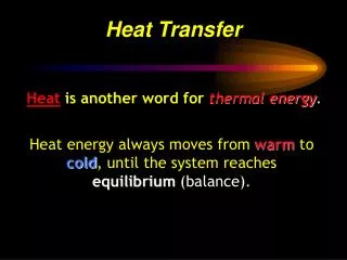
Motivation and Opportunities • Motivation • Waste heat, or low-grade heat, is often a “free” resource. • Many applications for cooling involve engines with a hot exhaust stream. • Burning fuel releases 10x to 100x the energy contained in batteries. • Current technology (microchannel heat exchangers and inexpensive expander/compressor machinery) is poised for commercial viability. • Opportunities (not an exhaustive list!) • Tactical cooling systems for the military use (current funder) • Automotive air-conditioning in current and new technology vehicles (hybrids). Also RVs, Trucks, Planes, etc. • Chem and bio protection suit cooling for first responders • Combined heat, cooling, and power systems for residential service • Auxiliary power unit (diesel, micro turbine, etc.) add-ons where cooling is needed
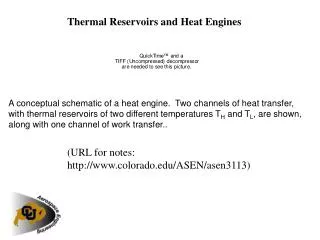
Basic Expander/Compressor Cycle Work Fluid Fluid Power Generating Components Cooling Components Condenser Qout QL QH Motive Fluid Cooling Fluid Vapor Compression Cycle Power Cycle
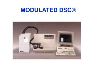
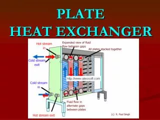
Key Technologies – MECS MECS – Microtechnology-based Energy and Chemical Systems • MECS relies on … • High rates of heat and mass transfer afforded by microchannels • Extremely high degree of control of processes • To miniaturize a wide range of systems … • Chemical (reactors, mixers, separators, etc.) • Energy (heat transfer devices, combustors, etc.) • Biological (biosensors, bioreactors, etc.) • Enabling portable and distributed systems
How it Works - Heat Exchangers Why? • • Large surface area • • Laminar flow • • Change in relative importance of phenomena and enables systems integration • e.g. boiling (surface tension) • better thermal management Results in smaller, cheaper, better
Considerations • Use Commercially Available Components Where Possible • Military Systems • Cost is not much of a consideration • Reliability, size, and weight are critical • Non-portable Commercial Systems • Cost is a driver • Reliability is important • Size and weight not critical • Portable (automotive?) Commercial Systems • Size, reliability, and cost are critical • Weight important, how much is driven by specifics
Completed Work – Breadboard Setup Pump Vaporizer Flow Meters Dyno Evaporator Expander/ Compressor
Summary of Breadboard Work • We have demonstrated a prototype expander/compressor operating at 150 W of cooling • Mean device efficiency was shown to be 65-70% at 1500 rpm—adequate to reach a COP of 0.7 at design conditions. • No regenerator was used in the breadboard system. • Follow-on work will include: • Investigate the thermodynamic effects of a regenerator in the power cycle. • Build and test a 2 kW split cycle heat activated cooler. • Build and test a 5 kW combined cycle cooler.
Completed Work – 2 kW System • Split Cycle E/C System • Separate power and vapor cooling cycles • Oil loop used for the power cycle for lubricating the expander • Built from both commercial and semi-custom components • Status • System has been assembled • Testing of the individual components and overall system complete • Performance data shows expander component requires higher efficiency.
Summary • We have demonstrated working systems with promising performance. • Key technology remains in the development phase – an expander with the requisite efficiency. • No regenerator has been used so far in our efforts. • Microchannel component demonstration will be shown on the next generation system.
Next Step – 5 kW System • 5 - kW system development is underway with modeling studies and expander development. • System will have a single fluid and a common condenser. • Microchannel heat transfer components will be included in the overall system. • Size, weight, and performance will be key issues to concentrate on.