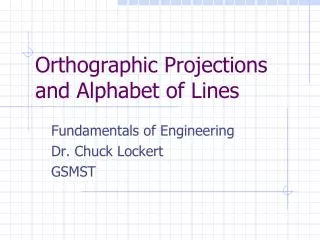
Orthographic Projections
Orthographic Projections. Mr. Johanson Technology Education Blue Mountain High School. What are Orthographic Projections. Orthographic Projections are a collection of 2-D drawings that work together to give an accurate overall representation of an object. Orthographic Projections.

Orthographic Projections
E N D
Presentation Transcript
Orthographic Projections Mr. Johanson Technology Education Blue Mountain High School
What are Orthographic Projections • Orthographic Projections are a collection of 2-D drawings that work together to give an accurate overall representation of an object.
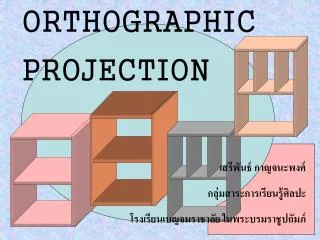
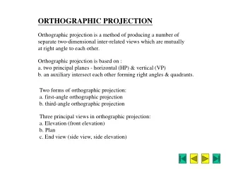
Orthographic Projections • These Projections define the 6 Principal views • Front • Top • Right Side • Left Side • Back • Bottom
Why Orthographic Projections? • We use orthographic projections as part of the Engineering Process • They allow us to see the Length, Width, and Height • They provide a basis for communication • They allow Engineers and other professionals to communicate specific details about a part, house, or product
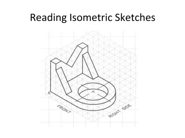
How do Orthographic Projections work? • Each view of an orthographic projections shows all the vertical and parallel lines and details associated with that object from that point of view. • Try thinking of it as if your putting something into a glass box Part in a glass box
The Glass box • Here we have the front view of the object projected onto the front of the glass box
The Glass Box • Notice how all the solid lines are only of the vertical and parallel lines. • The curved portion is not projected • For this reason Orthographic projections come in groups of drawings. • These drawings are typically called 3-view drawings, engineering drawings, or working drawings
The Glass Box • In this picture you can that the top view has been added to the glass box
The Glass Box • Now three views are present • Front, Top, Right Hand Side • These three views make up what is known as a 3-View Drawing
The Glass Box • Now it wouldn’t make much sense to generate drawings with a 3D drawing in a box surrounded with 2D projections around it and then try to dimension it • So we remove the 3D part and unfold the box to lay all three views out flat.
The Glass Box • This positioning is the standard positioning for an orthographic projection or 3-view drawing
What Does This Tell Us? • Positioning the drawings in this manner gives the reader a reference for reading the drawings • They tell us about the Length, Width, and Height of the part
3-View Drawings • With out all three drawings the features of the part cannot be accurately determined • All three must be present in order to get an understanding of all features of a part • With only one drawings misconceptions could be made about the part
Special Line • Some times there are features about a part that cannot be seen but are still there • Two common special line types are Hidden and Center lines
Hidden and Center Lines • Hidden lines allow the engineer to show features which are hidden from view. • Often times this is the result of features below the surface of a part such as a hole • Information such as the holes depth could not be determined with our the use of hidden lines
Hidden and Center Lines What do we know about the holes? How many are there? How deep are they? Do they intersect? All good questions, none of which can be answered from this drawing alone
Hidden and Center lines This would be the 3 view drawing with out hidden lines. Can the answers from the previous slide be answered?
Hidden and Center Lines Here are the same drawings with the hidden lines added. Now we can answer those questions from before. What do we know about the holes? How many are there? How deep are they? Do they intersect?
Hidden and Center Lines • Center lines tell us where the center of a hole is • This gives a point of reference for locating the hole • It also helps to inform the reader if the hidden lines they see are for a hole or some other type of feature
Hidden and Center Lines Now we can determine the center points of the holes and they also clue us into the fact that the hidden lines are representing holes
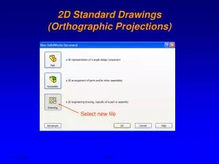
Dimensioning • Dimensioning is the process by which lengths, widths, and heights are displayed on a orthographic projection • Dimensioning should include all pertinent information about a part without cluttering the part with too many dimensionsons
Dimensioning • Once a feature has been dimensioned it need not be dimensioned again in the same drawing • Circles can be dimensioned with their diameter while arcs and curves should be dimensioned with their radius • Circles, arcs, and curves should have dimensions located their circle centers