Download
1 / 40
400 likes | 512 Views
Learn about structural, data, and control hazards in pipeline CPU design, along with hazards such as RAW, WAW, and WAR. Dive into dynamic scheduling techniques like Tomasulo's Algorithm to enhance processor performance by handling unknown dependencies at runtime.

E N D
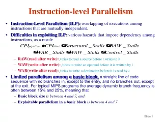
Recall from Pipelining Review • Pipeline CPI = Ideal pipeline CPI + Structural Stalls + Data Hazard Stalls + Control Stalls • Ideal pipeline CPI: measure of the maximum performance attainable by the implementation • Structural hazards: HW cannot support this combination of instructions • Data hazards: Instruction depends on result of prior instruction still in the pipeline • Control hazards: Caused by delay between the fetching of instructions and decisions about changes in control flow (branches and jumps)
Data Hazards Review • RAW (read after write) hazard: • instruction I occurs before instruction J in the program but… • …instruction J tries to read an operand before instruction I writes to it, so J incorrectly gets the old value • Example: … I:LW R1, 0(R2) … J: ADD R3, R1, R4 … • A RAW hazard is a true data dependence, where there is a programmer-mandated flow of data from one instruction (the producer) to another (the consumer) • therefore, the consumer must wait for the producer to finish computing and writing
Data Hazards Review • WAW (write after write) hazard: • instruction I occurs before instruction J in the program but… • …instruction J tries to write an operand before instruction I writes to it, so the wrong order of writes causes the destination register to end up with the value from I rather than that from J • Example: … I:SUB R1, R2, R3 … J: ADD R1, R3, R4 … • A WAW hazard is a not a true data dependence, but rather a kind of name dependence, called output dependence , because of the (avoidable?) same name of the destination registers • WAW hazards cannot occur in the classic 5-stage MIPS integer pipeline. Why…? • registers are written only in one stage, the WB stage, and • instructions enter the pipeline in order • However, we shall deal with situations where instructions may be executed out of order…
Data Hazards Review • WAR (write after read) hazard: • instruction I occurs before instruction J in the program but… • …instruction J tries to write an operand before instruction I reads it, so I incorrectly gets the later value • Example: … I:SUB R2, R1, R3 … J: ADD R1, R3, R4 … • A WAR hazard is a not a true data dependence, but rather a kind of name dependence, called antidependence, because of the (avoidable?) shared name of two registers • WAR hazards cannot occur in the classic 5-stage MIPS integer pipeline. Why…? • registers are read early and written late • instructions enter the pipeline in order • However, we shall deal with situations where instructions may be executed out of order…
Why Dynamic Scheduling…? Dynamic scheduling reduces this stall via ILP: Instruction Level Parallelism Stall instruction Static pipeline scheduling Yes Data Hazard Bypass possible Yes Bypass or Forwarding No No Pipeline processing Stall instruction Goal of ILP: To get as many instructions as possible executing in parallel while respecting dependencies
Reg Reg Reg Ifetch Ifetch Ifetch Ifetch DMem ALU Bubble ALU ALU Reg Reg DMem DMem Bubble Reg Reg Recall Data Hazard Resolution: In-order issue, in-order completion Time (clock cycles) I n s t r. O r d e r lwr1, 0(r2) sub r4,r1,r6 and r6,r2,r7 Bubble ALU DMem or r8,r2,r9 Extend to Multiple instruction issue? What if load had longer delay? Can and issue?
Reg Reg Reg Ifetch DMem’ DMem Add ALU In-Order Issue, Out-of-order Completion • Which hazards are present? RAW? WAR? WAW? • load r3 <- r1, r2 • add r1 <- r5, r2 • sub r3 <- r3, r1 or r3 <- r2, r1 • Register Reservations • when issue mark destination register busy till complete • check all register reservations before issue
Advantages ofDynamic Scheduling • Handles cases when dependences unknown at compile time • (e.g., because they may involve a memory reference) • It simplifies the compiler • Allows code that compiled for one pipeline to run efficiently on a different pipeline • Hardware speculation, a technique with significant performance advantages, that builds on dynamic scheduling
HW Schemes: Instruction Parallelism • Key idea: Allow instructions behind stall to proceedDIVD F0,F2,F4 ADDD F10,F0,F8SUBD F12,F8,F14 • Enables out-of-order executionand allows out-of-order completion • Will distinguish when an instruction begins execution and when it completes execution; between 2 times, the instruction is in execution • In a dynamically scheduled pipeline, all instructions pass through issue stage in order (in-order issue)
Dynamic Scheduling Step 1 • Simple pipeline has 1 stage to check both structural and data hazards: Instruction Decode (ID), also called Instruction Issue • Split the ID pipe stage of simple 5-stage pipeline into 2 stages: • Issue—Decode instructions, check for structural hazards • Read operands—Wait until no data hazards, then read operands
A Dynamic Algorithm: Tomasulo’s Algorithm • For IBM 360/91 (before caches!) • Goal: High Performance without special compilers • Small number of floating point registers (4 in 360) prevented interesting compiler scheduling of operations • This led Tomasulo to try to figure out how to get more effective registers — renaming in hardware! • Why Study 1966 Computer? • The descendants of this have flourished! • Alpha 21264, HP 8000, MIPS 10000, Pentium III, PowerPC 604, …
Tomasulo Algorithm • Control & buffers distributed with Function Units (FU) • FU buffers called “reservation stations”; have pending operands • Registers in instructions replaced by values or pointers to reservation stations(RS); • form of registerrenaming; • avoids WAR, WAW hazards • More reservation stations than registers, so can do optimizations compilers can’t • Results to FU from RS, not through registers, over Common Data Bus that broadcasts results to all FUs • Load and Stores treated as FUs with RSs as well • Integer instructions can go past branches, allowing FP ops beyond basic block in FP queue
Tomasulo Organization FP Registers From Mem FP Op Queue Load Buffers Load1 Load2 Load3 Load4 Load5 Load6 Store Buffers Add1 Add2 Add3 Mult1 Mult2 Reservation Stations To Mem FP adders FP multipliers Common Data Bus (CDB)
Reservation Station Components Op:Operation to perform in the unit (e.g., + or –) Vj, Vk:Value of Source operands • Store buffers has V field, result to be stored Qj, Qk:Reservation stations producing source registers (value to be written) • Note: Qj,Qk=0 => ready • Store buffers only have Qi for RS producing result Busy:Indicates reservation station or FU is busy Register result status—Indicates which functional unit will write each register, if one exists. Blank when no pending instructions that will write that register.
Three Stages of Tomasulo Algorithm 1. Issue—get instruction from FP Op Queue If reservation station free (no structural hazard), control issues instr & sends operands (renames registers). 2. Execute—operate on operands (EX) When both operands ready then execute; if not ready, watch Common Data Bus for result 3. Write result—finish execution (WB) Write on Common Data Bus to all awaiting units; mark reservation station available • Normal data bus: data + destination (“go to” bus) • Common data bus: data + source (“come from” bus) • 64 bits of data + 4 bits of Functional Unit source address • Write if matches expected Functional Unit (produces result) • Does the broadcast • Example speed: 2 clks for load, 3 clks for +/-, 10 clks for * ; 40 clks for /
Instruction stream 3 Load/Buffers FU count down 3 FP Adder R.S. 2 FP Mult R.S. Clock cycle counter Tomasulo Example
Tomasulo Example Cycle 2 Note: Can have multiple loads outstanding
Tomasulo Example Cycle 3 • Note: registers names are removed (“renamed”) in Reservation Stations; MULT issued • Load1 completing; what is waiting for Load1?
Tomasulo Example Cycle 4 • Load2 completing; what is waiting for Load2?
Tomasulo Example Cycle 5 • Timer starts down for Add1, Mult1
Tomasulo Example Cycle 6 • Issue ADDD here despite name dependency on F6?
Tomasulo Example Cycle 7 • Add1 (SUBD) completing; what is waiting for it?
Tomasulo Example Cycle 10 • Add2 (ADDD) completing; what is waiting for it?
Tomasulo Example Cycle 11 • Write result of ADDD here? • All quick instructions complete in this cycle!
Tomasulo Example Cycle 15 • Mult1 (MULTD) completing; what is waiting for it?
Tomasulo Example Cycle 16 • Just waiting for Mult2 (DIVD) to complete
Tomasulo Example Cycle 56 • Mult2 (DIVD) is completing; what is waiting for it?
Tomasulo Example Cycle 57 • Once again: In-order issue, out-of-order execution and out-of-order completion.
Tomasulo Drawbacks • Complexity • delays of 360/91, MIPS 10000, Alpha 21264, IBM PPC 620 in CA:AQA 2/e, but not in silicon! • Many associative stores (CDB) at high speed • Performance limited by Common Data Bus • Each CDB must go to multiple functional units high capacitance, high wiring density • Number of functional units that can complete per cycle limited to one! • Multiple CDBs more FU logic for parallel assoc stores • Non-precise interrupts! • We will address this later
Superscalar Architecture • A superscalar processor executes more than one instruction during • a clock cycle by simultaneously dispatching multiple instructions to • redundant functional units on the processor. • Each functional unit is not a separate CPU core but an execution resource • within a single CPU Superscalar Pipeline Typical 5-stage pipeline
Conclusion Pipeline design and scheduling are techniques to achieve significant throughput improvement in modern CPU. 20-stage pipeline