Download
1 / 55
550 likes | 570 Views
Learn how to calculate currents and voltages in circuit components connected in series and parallel, using Kirchoff's Rules. Identify series and parallel connections and calculate equivalent resistances. Practice solving example circuits.

E N D
Today’s agenda: Resistors in Series and Parallel. You must be able to calculate currents and voltages in circuit components in series and in parallel. Kirchoff’s Rules. You must be able to use Kirchoff’s Rules to calculate currents and voltages in circuit components that are not simply in series or in parallel.
Resistances in Circuits Recall from lecture 7: • two simple ways to connect circuit elements Series: A B Parallel: A B Circuit elements can be connected neither in series nor in parallel.
Identifying series and parallel connections A B If you can move your finger along the wires from A to B without passing a junction, i.e., without ever having a choice of which wire to follow, the components are connected in series.
In contrast: ??? A B If you ever have a choice of which wire to follow when moving from A to B, the circuit elements are not in series. If each element provides an alternative path between the same points A and B, the elements are in parallel. Circuit elements can be connected neither in series nor in parallel.
Are these resistors in series or parallel? - + V parallel Not enough information: It matters where you put the source of emf.
Are these resistors in series or parallel? - V + series It matters where you put the source of emf.
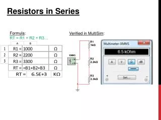
Resistors in series R1 R2 R3 A B I I V1 V2 V3 I I - + V Current: same current flows through all resistors (conservation of charge: all charge entering the series of resistors at A must leave it at B) Voltage: voltages in a series add up VAB=V1+V2+V3 (loop rule, see last lecture, reflecting conservation of energy)
Equivalent resistance Req R1 R2 R3 A B I I V1 V2 V3 I I I V V - + - + Replace the series combination by a single “equivalent” resistor (producing same total voltage for same current) V = V1 + V2 + V3 V = IR1 + IR2 + IR3 V = IReq IR1 + IR2 + IR3 = IReq R1 + R2 + R3 = Req
Generalize this to any number of resistors: • resistances in series add up! Note: for resistors in series, Req is always greater than any of the Ri.
Resistors in parallel R1 I1 Current: • current I splits into currents I1, I2, I3 I = I1+ I2+ I3 (conservation of charge) V R2 I2 B A V R3 • Voltage: • Voltage drops across all three resistors are identical • VAB= V1= V2= V3 (conservation of energy) I3 V I - + V
Equivalent resistance R1 I1 Req A B V R2 I2 B A I V - + V R3 I3 Replace parallel combination by single equivalent resistor V I V - + I = I1+ I2+ I3 Dividing both sides by V gives
Generalize this to any number of resistors: • for resistors in parallel, the inverse resistances add Note: for resistors in parallel, Req is always less than any of the Ri.
Summary: Series B A same I, V’s add Parallel A B same V, I’s add
Example: calculate the equivalent resistance of the resistor “ladder” shown. All resistors have the same resistance R. A B Let’s discuss the strategy!
Where to start? Series A B
new color indicates an equivalent resistor made up of several original ones Parallel A B
Series A B
Parallel A B
Series A B
All done! A B
Example: For the circuit below, calculate the current drawn from the battery and the current in the 6 resistor. 10 8 6 3 8 1 9 V Work the example at the blackboard in lecture.
Strategy: Identify “bite-sized chunks” 10 8 6 3 8 1 9 V Replace parallel combination (green) by its equivalent.
Any more “bite-sized chunks?” 10 4 6 3 1 9 V Replace the series combination (blue box) by its equivalent.
10 10 3 1 9 V Replace the parallel combination (orange) by its equivalent. We are left with an equivalent circuit of 3 resistors in series, which is easy handle.
Now perform the actual calculation a step at a time. R1=10 R3 and R4 are in parallel. R3=8 R2=6 R5= 3 R4=8 R6=1 =9 V R1=10 R2 and R34 are in series. R2=6 R34=4 R5= 3 R6=1 =9 V
Let’s shrink the diagram a bit, and work this a step at a time. R1=10 R1 and R234 are in parallel. R234=10 R5= 3 R6=1 =9 V R1234, R5 and R6 are in series. R1234=5 R5= 3 R6=1 =9 V
Calculate the current drawn from the battery. R1234=5 R5= 3 R6=1 =9 V I=1 A
Find the current in the 6 resistor. R1=10 R3=8 There are many ways to do the calculation. This is just one. R2=6 R5= 3 R4=8 R6=1 I=1 A =9 V R1=10 V1 = V234 = V1234 (parallel). R234=10 R5= 3 I=1 A R6=1 =9 V
Find the current in the 6 resistor. I V1234 = I R1234 = (1)(5) = 5 V R1234=5 R5= 3 V1 = V234 = 5 V I=1 A R6=1 =9 V R1=10 V234 = I234 R234 I234 I234 = V234 / R234 = 5/10 R234=10 R5= 3 I234 = 0.5 A I=1 A R6=1 =9 V
Find the current in the 6 resistor. R1=10 R3=8 I2=I234 I234 = I2 = I34 = 0.5 A R2=6 R5= 3 I2 = 0.5 A R4=8 R6=1 I=1 A =9 V
Find the current in the 6 resistor. R1=10 A student who has taken a circuits class will probably say R234=10 R5= 3 R1 = R234 so I1 = I234 = I/2 = 0.5 A R6=1 I=1 A =9 V If you want to do this on the exam, make sure you write down your justification on the exam paper, and don’t make a mistake! If you don’t show work and make a mistake, we can’t give partial credit. Answers without work shown generally receive no credit.
Example: two 100 light bulbs are connected (a) in series and (b) in parallel to a 24 V battery. For which circuit will the bulbs be brighter? • parallel (left) • series (right)
Example: two 100 light bulbs are connected (a) in series and (b) in parallel to a 24 V battery. What is the current through each bulb? For which circuit will the bulbs be brighter? (a) Series combination. R1 100 R2 100 Req = R1 + R2 - + V = I Req I V = 24 V V = I (R1 + R2) I = V / (R1 + R2) = 24 V / (100 + 100 ) = 0.12 A
Example: two 100 light bulbs are connected (a) in series and (b) in parallel to a 24 V battery. What is the current through each bulb? For which circuit will the bulbs be brighter? I1 R1 (b) Parallel combination. V I2 R2 V - + V = 24 V I I (because R1 = R2)
Example: two 100 light bulbs are connected (a) in series and (b) in parallel to a 24 V battery. What is the current through each bulb? For which circuit will the bulbs be brighter? Calculate the power dissipated in the bulbs. The more power “consumed,” the brighter the bulb. In other words, we use power as a proxy for brightness.
Example: two 100 light bulbs are connected (a) in series and (b) in parallel to a 24 V battery. What is the current through each bulb? For which circuit will the bulbs be brighter? (a) Series combination. R1 100 R2 100 for each bulb: - + I V = 24 V P = I2R P = (0.12 A)2 (100 ) P = 1.44 W
Example: two 100 light bulbs are connected (a) in series and (b) in parallel to a 24 V battery. What is the current through each bulb? For which circuit will the bulbs be brighter? I1 R1 (b) Parallel combination. V I2 R2 for each bulb: V I I P = V2 / R - + P = (24 V)2 / ( 100 ) V = 24 V P = 5.76 W We also know each current, so we could have used P = I2R.
Example: two 100 light bulbs are connected (a) in series and (b) in parallel to a 24 V battery. What is the current through each bulb? For which circuit will the bulbs be brighter? I1 R1 V R1 100 R2 100 I2 R2 - + V I I I V = 24 V - + V = 24 V Compare: Pseries = 1.44 W Pparallel = 5.76 W The bulbs in parallel are brighter.
This is what you see if you connect 40 W bulbs directly to a 120 V outlet. (DO NOT TRY AT HOME.) On Off
Today’s agenda: Resistors in Series and Parallel. You must be able to calculate currents and voltages in circuit components in series and in parallel. Kirchoff’s Rules. You must be able to use Kirchoff’s Rules to calculate currents and voltages in circuit components that are not simply in series or in parallel.
h 30 I1 40 1 2 = 45 V I3 a d c b 20 I2 1 = 85 V 1 g e f A nontrivial circuit Analyze this circuit for me, please. Find the currents I1, I2, and I3.
h 30 I1 40 1 2 = 45 V I3 a d c b 20 I2 1 = 85 V 1 g e f Two sets of resistors in series. This. And this. Further analysis is difficult. series1 seems to be in parallel with the 30 resistor, but what about 2? We need new tools to analyze that combination. series1 series2
Kirchhoff’s Rules Kirchhoff’s Loop Rule: (see last lecture) The sum of potential changes around any closed path in a circuit is zero. Energy conservation: a charge ending up where it started neither gains nor loses energy (Ui = Uf ) Kirchhoff’s Junction Rule: The sum of all currents entering a junction must equal the sum of all currents leaving the junction Charge conservation: charge in = charge out (current in counts +, current out counts -)
Recipe for problems that require Kirchhoff’s rules 1. Draw the circuit. 2. Label the current in each branch of the circuit with a symbol (I1, I2, I3, …) and an arrow (direction). 3. Apply Kirchhoff’s Junction Rule at each junction. Current in is +, current out is -. 4. Apply Kirchhoff’s Loop Rule for as many independent loops as necessary (pick travel direction and follow sign rules). Resistor: Battery: + - V is - V is + I travel travel 5. Solve resulting system of linear equations.
h 30 I1 I3 40 1 2 = 45 V a a d d c b 20 I2 1 = 85 V 1 g e f Back to our circuit: 3 unknowns (I1, I2, and I3), so we will need 3 equations. We begin with the junctions. Junction a: I3 – I1 – I2 = 0 --eq. 1 Junction d: -I3 + I1 + I2 = 0 Junction d gave no new information, so we still need two more equations.
h 30 I1 I3 40 1 2 = 45 V a d c b 20 I2 1 = 85 V 1 g e f Loop 1. Loop 2. Loop 3. There are three loops. Any two loops will produce independent equations. Using the third loop will provide no new information.
h 30 I1 40 1 2 = 45 V I3 a d c b 20 I2 1 = 85 V 1 g e f The “green” loop (a-h-d-c-b-a): (- 30 I1)+ (+45) + (-1 I3) + (- 40 I3) = 0 (- 30 I1) + (+45)+ (-1 I3) + (- 40 I3) = 0 (- 30 I1) + (+45) + (-1 I3)+ (- 40 I3) = 0 (- 30 I1) + (+45) + (-1 I3) + (- 40 I3)= 0 (- 30 I1) + (+45) + (-1 I3) + (- 40 I3) = 0 I + - V is - V is + travel travel
h 30 I1 40 1 2 = 45 V I3 a d c b 20 I2 1 = 85 V 1 g e f The “blue” loop (a-b-c-d-e-f-g): (+ 40 I3) + ( +1 I3) + (-45) + (+20 I2) + (+1 I2) + (-85) = 0 (+ 40 I3) + ( +1 I3) + (-45) + (+20 I2) + (+1 I2) + (-85)= 0 (+ 40 I3) + ( +1 I3) + (-45) + (+20 I2) + (+1 I2) + (-85) = 0 (+ 40 I3) + ( +1 I3) + (-45) + (+20 I2) + (+1 I2) + (-85) = 0 (+ 40 I3) + ( +1 I3)+ (-45) + (+20 I2) + (+1 I2) + (-85) = 0 (+ 40 I3) + ( +1 I3) + (-45) + (+20 I2) + (+1 I2) + (-85) = 0 (+ 40 I3) + ( +1 I3) + (-45)+ (+20 I2) + (+1 I2) + (-85) = 0 I + - V is - V is + travel travel
After combining terms and simplifying, we now have three equations, three unknowns; the rest is “just algebra.” Junction a: I3 – I1 – I2 = 0 --eq. 1 The “green” loop - 30 I1 + 45 - 41 I3 = 0 --eq. 2 The “blue” loop 41 I3 -130 + 21 I2 = 0 --eq. 3 skip the algebra! Make sure to use voltages in V and resistances in . Then currents will be in A. You can see the solution in part 7 of today’s lecture notes
Collect our three equations: I3 – I1 – I2 = 0 - 30 I1 + 45 - 41 I3 = 0 41 I3 -130 + 21 I2 = 0 Rearrange to get variables in “right” order: – I1 – I2 + I3 = 0 - 30 I1 - 41 I3 + 45 = 0 21 I2 + 41 I3 -130 = 0 Use the middle equation to eliminate I1: I1 = (41 I3 – 45)/(-30) There are many valid sets of steps to solving a system of equations. Any that works is acceptable.