Download
1 / 29
290 likes | 309 Views
Understand the process of designing functional, stable, and sustainable stream channels. Learn about soil bioengineering, channel form, and key design components. Explore the comparison of geomorphic channel design and soil bioengineering.

E N D
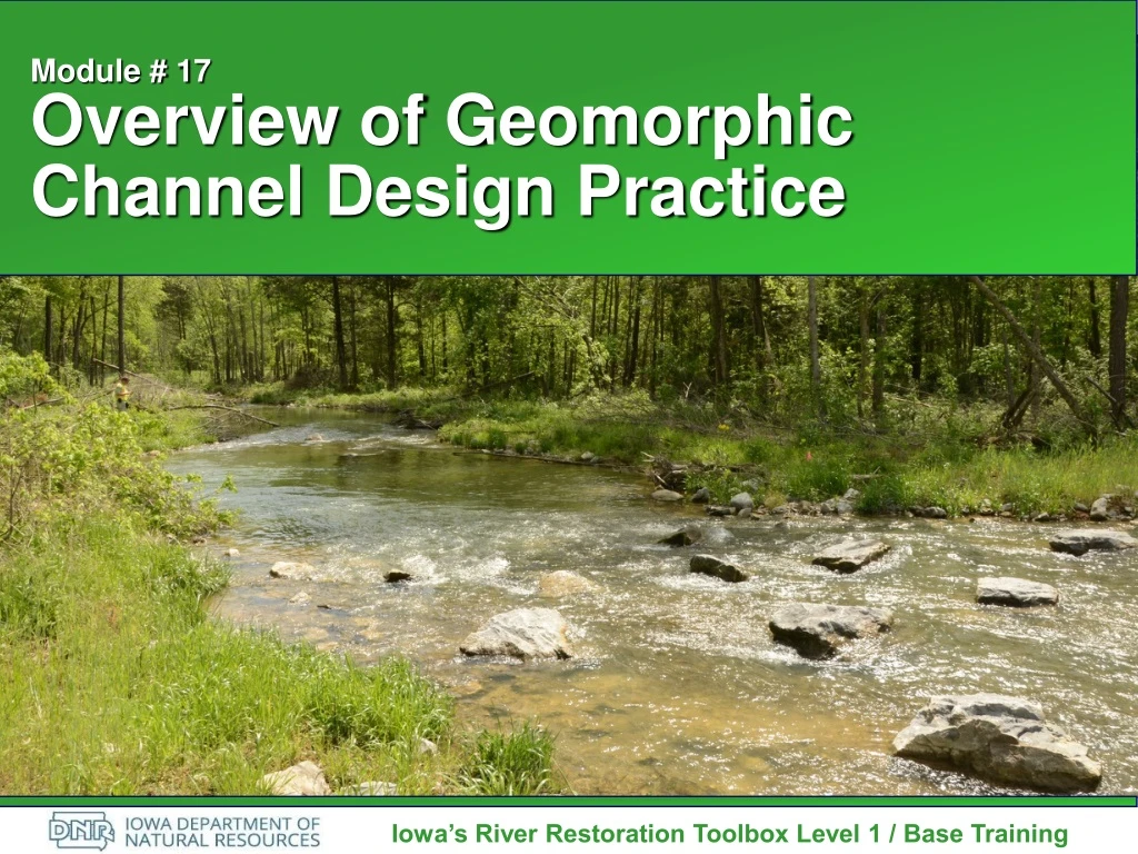
Module # 17Overview of Geomorphic Channel Design Practice Iowa’s River Restoration Toolbox Level 1 / Base Training
Geomorphic Channel Design Process by which new or re-constructed stream channels and their associated floodplain riparian systems are designed to be naturally functional, stable, healthy, productive, and sustainable.
Soil Bioengineering The use of living and non-living materials to provide soil reinforcement and prevent erosion
Channel Design Stream System and Processes Disturbed Section Design of Channel Form Channel Form Not Altered Channel Dimensions Critical Vegetation Critical Bankfull Discharge Bankfull Depth Design Parameters Vary Typically Constant In-Stream Construction Streambank Construction Sediment Transport Slope Stability Comparison of Geomorphic Channel Design and Soil Bioengineering Soil Geomorphic Bioengineering
Geomorphic Channel Design Components • Analog • Empirical • Analytical
Form Vs Process • Not Mutually Exclusive • Process Drives Form • Must Consider Time Scale as Part of Design Process • Ultimately Must Design and Build a Stream Form • Can Create Backlash Towards the Profession
Primary Reference Stream Restoration Design National Engineering Handbook Part 654 Released, August 2007 (vs. 031908) Chapter 11: Geomorphic Approach for Natural Channel Design USDA NRCS, Stream Restoration Design Handbook, 2007. U.S. Department of Agriculture Natural Resources Conservation Service
Phases of Geomorphic Channel Design (NCD Approach) • Define Restoration Objectives • Develop Regional & Localized Specific Geomorphic and Hydraulic Data • Conduct Watershed/River Assessment • Assess Potential for Passive Restoration (i.e. Land Use Changes) • Initiate Geomorphic Channel Design w/ Analytical Testing of Hydraulics & Sediment Transport • Design Stabilization/Enhancement Measures • Implement Proposed Design • Design & Implement Monitoring & Maintenance Plan
Define Restoration Objectives • Flooding Issues • Streambank Stability • Reduction in Sediment Supply • Improved Fish Habitat & Biological Diversity • Self Maintenance /Natural System • Aesthetics • Mitigation Needs
Develop Regional & Localized Specific Geomorphic and Hydraulic Data • Identify Valley Type & Stream Type • Obtain Reference Reach Data for Intended Stream Type • Compare Impacted Reach and Reference Reach Data to Regional Curves • Convert Reference Reach Data to Dimensionless Ratios • Calculate Bankfull Discharge & Velocity
Locating Reference Reaches • Same Stream as Impacted Reach • Same General Watershed • Review Gazetteer Maps for Similar Pattern Streams as Intended Design • Be Prepared to Drive to Numerous Sites • Reference Reaches are Typically not Found at Bridges and Culverts!!
Reference Reach Criteria • Stable Reference Stream in Same Hydro-Physiographic Region • Same Stream Type as Intended Design • Stable for Two Meander Wavelengths (20 Bankfull Widths) • Best if Similar Valley Slope and Sediment Regime as Impacted/Design Reach
Dimensionless Ratios • Key Element in the Geomorphic Approach to Natural Channel Design • Used to “Size” a Reference Stream to a Designed Stream • Requires Numerous Geomorphic Measurements • Make “Dimensionless” Geomorphic Measurements by Dividing by a Bankfull Parameter • In Order to Capture Stream’s Natural Variability, Need a Range of Dimensionless Ratios • Used to Design Pool/Riffle/Glide/Run Habitat
Dimensionless Ratios Wbkf = 20 Lm = 200 Feet
Dimensionless Ratios Lm/Wbkf = 200/20=10 Wbkf = 20 Lm = 200 Feet
Wbkf = 10 Wbkf = 20 Lm = 100 Feet Lm = 200 Feet Dimensionless Ratios Reference Reach Designed Reach
Primary Dimensionless Ratios – Cross Sectional Dimensions • Pool, Run, or Glide • Feature Area/Riffle Bankfull Area • Max. Feature Depth/Mean Riffle Bankfull Depth • Mean Feature Depth/Mean Riffle Bankfull Depth • Feature Width/Riffle Bankfull Width
Primary Dimensionless Ratios – Pattern • Meander Wavelength (Lm)/Riffle Bankfull Width (Wbkf) • Radius of Curvature (Rc)/Riffle Bankfull Width (Wbkf) • Beltwidth (Wblt)/Riffle Bankfull Width (Wbkf) = MWR • MWR = Meander Width Ratio
Primary Dimensionless Ratios – Profile • Slope • Riffle Slope/Bankfull Slope • Pool Slope/Bankfull Slope • Run Slope/Bankfull Slope • Glide Slope/Bankfull Slope • Pool Spacing • Pool to Pool Spacing/Riffle Bankfull Width • Pool Length/Riffle Bankfull Width • Maximum Depths • Max. Riffle Depth/Mean Riffle Bankfull Depth • Max. Pool Depth/Mean Riffle Bankfull Depth • Max. Run Depth/Mean Riffle Bankfull Depth • Max. Glide Depth/Mean Riffle Bankfull Depth
Geomorphic Data Collection • Site Review/Toothpick Survey • Cross Sections • Longitudinal Profiles • Pebble Counts/Sediment Samples • Stream Assessments
Profile Analysis • Bankfull Slope • Facet Slopes – Always Measure Water Surface • Pool to Pool Spacing • Pool Lengths • Facet Maximum Depths – Channel Bottom to Bankfull Elevation • Low Bank Height or Valley Bottom
Cross Sections • Bankfull Call/Elevation • Inner Berm Features • Floodprone Width • Bankfull Area • Bankfull Width and Depth
Pebble Counts & Bar Samples 3. Obtain Sieve Analysis at the location of the largest particle on lower 1/3 of point bar or other depositional feature 1. Obtain a 100-particle pebble count on 10 transects from bankfull to bankfull throughout the reach (Classification) 2. Obtain a 100-particle pebble count in the riffle bed (Sediment Transport)
Design Reach Data Collection • Dependant Upon Purpose of Project • Impacted Reach (Minimum Data per Stream Type) • Planform Measurements • Riffle Cross Section • Reach Average Pebble Count • Riffle Bed Material Pebble Count • Bar Sample Sieve Analysis • Longitudinal Profile
Reference Reach Data Collection • Planform Measurements • Facet Cross Sections (Riffle, Run, Pool & Glide) • Longitudinal Profile through 2 Meander Wavelengths (Minimum) or 20 to 30 Bankfull Widths • Reach Average Pebble Count • Riffle Bed Material Pebble Count • Bar Sample Sieve Analysis • Pfankuch Channel Stability Assessment • Site Controls (Bedrock, Wood)
100 B A Ref 10 Bankfull Width (feet) Field Measurement Eastern U.S. Buffalo Run 1 0.1 1.0 10.0 Drainage Area (square miles) Compare Impacted & Reference Reach Data to Regional Curves • Make Comparison to Help Validate Data • Need to Use Regional Curves from Same Hydro-physiographic Area • If No Curves Exist Consider Developing Smaller Scale, Site Specific Curves
Calculate Bankfull Velocity & Discharge • Velocity Equations • Manning’s • Chezy • Darcy-Weisbach • Relative Roughness R/D84 • Discharge Equation • Q = U*A
Sediment Transport Validation • Stop, Store, and/or Transport Sediment Delivered to the System • Procedures for Gravel Systems Typically Based on Sediment Transport Competency and Capacity • Procedures for Sand Systems Typically Based on Sediment Transport Capacity
Module # 17Overview of Geomorphic Channel Design Practice Iowa’s River Restoration Toolbox Level 1 / Base Training