
Microcontrollers: Types, Applications, and Structures
E N D
Presentation Transcript
Microcontroller • A microcontroller (uC) is practically a microcomputer in one integrated circuit. • There is no perfect definition, there are types with different complexities. • Earlier types had a few more functions than simple processors • Modern types resemble the functions of a computer from a few years ago
Microcontroller Difference from „big” computers (eg.PCs): • lower calculation speed, capabilities • lower power consumption • lower memory (often hard to expand) • special peripherials are integrated, including program memory and RAM • „give it power supply and it works”
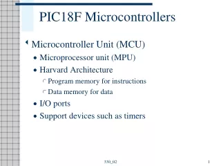
Microcontroller • Modern types typically (can) contain: • processor core • program memory (EEPROM/Flash) • RAM; data EEPROM • clock generator • digital I-O, serial ports, analog input, PWM output • timers, counters, event registering, interrupt capabilities
Microcontroller Application areas: • simpler „embedded systems” (controlling circuit of devices) • eg. vehicles, model vehicles, satellites, industrial robots, measurement devices, hobby devices, household devices • PC also has them (eg. as peripherial control units)
Microcontroller • 8bit types typically <20MHz clock, program memory from a few 1000.. 10000 words, a few 100B to few kB RAM • Processor parameters comparable to a 80’s PC (but those had usually larger RAM and storage). Easy to program in assembly.
Microcontroller 32bit types can be up to 100MHz clock, megabytes of flash, hundred kBs of RAM Can be similar to a 90’s PC. Simpler to program in C for example than in asm.
Structure • Microcontrollers are usually built with Harvard architecture, ie. separate bus and memory for program (now usually EEPROM or Flash) and for data memory. Data memory is of two types: volatile random access memory (SRAM) and sometimes also a separate non-volatile data memory (EEPROM) for data needed by the program. • RAM is made of 8b cells. Program memory can have cells >8b (so that it can contain instruction code and parameter as well)
Structure Harvard-architecture: separate program and data memory with separate buses
PIC microcontrollers „PIC” is the family of microcontrollers made by company „Microchip”. There are 8b, 16b and 32b families, with sub-families and dozens (hundreds) of types. 8bit family notations: lower range: PIC10, PIC12 middle range: PIC12, PIC16 upper range: PIC18 Naming: eg. PIC16F887 : of the PIC16 family, Flash prg memory, 887 type (which is closely related to other 88x types)
PIC10: <1k flash, 16..64B RAM, 6pin, 4..16MHz max, 8b ADC, 1..2 8b timer PIC12: 1..4k flash, 25..256B RAM, 8pin, 4..32MHz max, 10b ADC, 1..4 timers (8b / 16b) PIC16: 1..56k flash, 25B..4kB RAM, 8..64pin, 16..64MHz max, 10b ADC, 1..6 timers, UART, MSSP, etc. PIC18: 4..128k flash, 256B..4kB RAM, 18..100 pin, 32..64MHz max, special peripherials, extended instruction set PIC 8b families
Example: PIC16F690 block diagram Digit. ports Flash program memory RAM peripherials ALU
PIC16F690 pinout example Writing a byte into a PORT register can change the value of 8 pins at once. It is also possible to manipulate one bit (pin) at a time with single instructions. This is typical of microcontrollers. In microprocessors, bit manipulation has to be made by „masking”, by logical instructions (and, or etc) Microcontroller pins are multiplexed because of the high number of possible functions. You can choose the function of each pin in runtime from software (by writing to config registers in RAM). Most pins are on default digital (binary) input or output. These are usually grouped by 8 into ports, such as PORTA, PORTB, PORTC etc. with pins RA0..7 etc.
PIC16 program memory structure When the device gets power supply (or is reset), the program starts running from address 0. Address 4 is the interrupt vector. When there is an interrupt, the program will jump here. The cause of the interrupt has to be found from the interrupt flag bits. There is a separate 8 level stack. This is used to save the program counter (PC) contents when jumping to interrupt or executing a call instruction (a subroutine). Prg.mem can be made up of several pages (similar to banks in RAM)
PIC16F690 RAM structure SFR: special function registers GPR: general purpose registers Banks (pages)
PIC RAM In PIC 8b, there is no separate processor registers and RAM, the two are the same. (Eg. in Atmel controllers, there is a separate small register bank and a separate bigger RAM, similarly to microprocessor systems). PIC RAM’s 8b cell are called registers. There are two types: GPR (General Purpose Registers) are the traditional RAM, freely write/read. Store your variables here. SFR (Special Function Registers) are practically a realization of „memory mapped IO”. These registers can contain configuration info for the uC or peripherials, or used to access input-output data for peripherials. These can usually be freely read-written, but there are exceptions. Eg. register TRISA is used to set up the direction of pins of PORTA (in or out). The PORTA register contains the values of the pins – read it if it’s input, write to it if it’s output. Eg. if UART is configured, writing to TXD will send that byte out into serial port with proper framing.
PIC RAM • Often the physical size of RAM is larger than what the uC can access (the address bus width is smaller than needed). In such a case the RAM is divided into banks (pages). Only one bank can be reached at a time. • STATUS register is at the same address in all banks therefore can always be accessed. Its RPx bits setup which bank is currently selected. • In the assembler (asm compiler program) the directive „banksel” helps ease this. Eg. „banksel PORTA” will substitute it with an instruction to select the bank which contains the PORTA register. An include file is usually needed for this so the assembler knows the memory map.
PIC16 instruction set • PIC16 family instructions are 14bit long (one „word”) • This includes the opcode (the instruction itself) and a parameter which can be a constant („literal”) or a RAM address („file register”) and can contain a bit address in addition.
Instruction set briefing arithmetic: • add • subtract • increment, decrement logical: • and • or • xor • complement bitwise • bit set, bit clear • bit test • rotate (shift) • swap conditinal: • inc/dec, skip if zero • bit test, skip is set/clear data: • move control: • goto • call, return • nop (no operation) 18F family has an extended instruction set. Eg. hardware 8bx8b multiplier, more types of conditional branching etc.
Power supply • 8b PICs need typically 5V or 3.3V power supply voltage. High-end versions typically run on 3.3V • 5V versions often can operate from 2.5V to 5.5V. The 3.3V versions don’t like to get higher voltages. • The output high level is about equal to the positive supply voltage. • The input levels must usually not exceed the supply voltages! (There are special exceptions.)
Clock generation. Most types also have a totally built-in RC generator. For PIC16 this is usually 8MHz which can be divided. Quartz is more precise and stable, has less temperature dependency than RC oscillators. Esp. recommended for higher frequencies (eg. if you need USB etc.).
Clock • System clock (fs): the base clock signal • Instruction clock finstr= fs/4, for executing instructions • Almost all instructions need one Tinstr to execute (that’s why they are of same size). Branching instructions (goto, call) need two cycles (because they clear the pipeline). • Eg. fs=4MHz, then Tinstr=1us for instr. execution time.
Digital I/O • Most pins can be set up for digital input or output. • TRISx registers set directions for PORTx pins. • PORTx registers contain actual values of pins. • A pin set to input has large impedance. So to make a tristate port the hi-Z state is achieved by changing the pin to input. (The TRIS register name comes from tri-state). • The binary 1 output voltage is determined by power supply voltage. • Input levels should not exceed supply in either direction.
Digital IO matching • If connecting 5V and 3.3V devices • An 5V device will read a 3.3V level as logical 1. Zero is zero of course. • 3.3V device doesn’t like 5V level, use for example a resistor divider! • Diode, Z-diode protections can be useful. • If you need to change 3.3V to 5V, use transistors (be careful that one transistor will result in inverting the bit)
Switch to digital port The R is needed to give a proper voltage when the switch is off. The C helps to decrease the „bouncing” effect (a high freq noise when switching). If it’s not enough, use a Schmitt-trigger input gate (eg an inverter) between this circuit and the uC or use software solutions (eg. don’t allow the next switching to trigger sooner than eg. a few ms)
ADC (Analog digital converter) Often one or two ADC units are built in. A multiplexer can help to connect it to a lot of input pins. 8b PICs usually have a 10b successive approximation ADC that generates the result in 11 cycles (the cycle time can be setup)
Timer/counter • Timer function: the content of timer register is incremented with fs/4 frequency (ie +1 at every Tinstr) • 8b or 16b register • Prescale: increment for every n_th Tinstr (usu 1:1, 1:2, 1:4, 1:8, 1:16 ) • Counter: counts the impulses (edges) of external signal
Capture/compare • Capture mode: if there is a falling or rising edge on an input, saves the timer value • Compare mode: activates when timer reaches a previously setup value
PWM • PWM mode: auto puts a square wave on an output, freq and duty cylce programmable (pulse width modulation) • good for controlling lot of stuff (motors, heating, lamps, etc) • usually used to drive a MOSFET which then drives the target device • remember the uC output current is limited!
UART/USART/EUSART • universal asynchron. receiver transmitter • simple NRZ coded duplex serial port • can realize RS232 simple version • Rx and Tx (RD and TD) pins realized • 8b frame, no parity • as output is 0V..+supply; and RS232 is +- supply, you may need a matching circuit, eg. MAX232
UART coupling uC<->PC Max232 IC makes 0..5V into +- voltages (about +-8V or so) using a charge pump (that needs those capacitors)
MSSP • master synchronous serial port • for I2C and SPI
other ports • Special PICs (in PIC18 family) can have: • USB logical driver • CAN logical driver • Ethernet logical driver • (usually need an external physical driver IC for voltage/current/impedance matching)
Serial programming synchronous serial programming using a „programmer” hardware connected to PC VPP is the programming voltage (>Vsupply to indicate prg mode) ICSPDAT is data ICSPCLK is clock VDD (+3.3 / +5V) and VSS (Gnd) are connected as well. VDD Either supplied by programmer hardware or externally.
Serial programming For uC with larger memory and serial port you can use a bootloader. This is a small program at the start of the prg memory. This acts like a simple operating system. It initializes the serial port and then you can connect directly to PC (without programmer) and download user programs to the uC. The bootloader then can start the user program. Of course this reduces the available memory and the bootloader still needs to be programmed using a programmer hw.
More similar to trad. processors than PIC Load-store architecture: has a separete processor register set and separate big RAM; data from RAM must be copied to register to work on (in and out instructions) eg. Atmega 8: 32 general purpose working registers and 1kB RAM. It has 130 instructions (but is called a RISC architecture). Instructions are 16 or 32b long. Stack is realised in RAM. interrupts have separate vectors in table Atmel 8b uCs
Raspberry Pi 32b panel • microSD card slot • HDMI and composite video out • audio out • USB • ethernet • ARM processor • can run Linux • practically a complete modern computer