Download
1 / 20
200 likes | 387 Views
Radar Principles and Systems Part I. Learning Objectives. Comprehend basic operation of a simple pulse radar system and a simple continuous wave radar system Know the following terms: pulse width, pulse repetition frequency, carrier frequency, peak power, average power, and duty cycle

E N D
Learning Objectives • Comprehend basic operation of a simple pulse radar system and a simple continuous wave radar system • Know the following terms: pulse width, pulse repetition frequency, carrier frequency, peak power, average power, and duty cycle • Know the block diagram of a simple pulse radar system
Learning Objectives • Comprehend the concept of Doppler frequency shift • Know the block diagram of a simple continuous wave radar system (amplifiers, power amplifiers, oscillators, and waveguides) • Comprehend the use of filters in a CW radar system
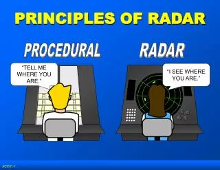
Two Basic Radar Types • Pulse Transmission • Continuous Wave
Pulse Transmission • Pulse Width (PW) • Length or duration of a given pulse • Pulse Repetition Frequency (PRF) • Frequency at which consecutive pulse are transmitted • Pulse Repetition Time (PRT=1/PRF) • Time from beginning of one pulse to the next • Inverse of PRF • PW determines radar’s • Minimum detection range • Maximum detection range • PRF determines radar’s • Maximum detection range
Pulse Radar Components Synchronizer Transmitter RF Out Power Supply Duplexer ANT. Echo In Display Unit Receiver Antenna Control
Continuous Wave Radar • Continual energy transmission • Separate transmit/receive antennas • Relies on “DOPPLER SHIFT”
Doppler Frequency Shifts Motion Away: Echo Frequency Decreases Motion Towards: Echo Frequency Increases
Continuous Wave Radar Components Antenna Transmitter CW RF Oscillator OUT IN Discriminator Mixer AMP Antenna Indicator
Pulse Echo Single antenna Gives range, usually altitude as well Susceptible to jamming Range determined by PW and PRF Continuous Wave Requires 2 antennae Range or Altitude info High SNR More difficult to jam but easily deceived Can be tuned to look for frequencies Pulse Vs. Continuous Wave
RADAR Wave Modulation • Amplitude Modulation • Vary the amplitude of the carrier sine wave • Frequency Modulation • Vary the frequency of the carrier sine wave • Pulse-Amplitude Modulation • Vary the amplitude of the pulses • Pulse-Frequency Modulation • Vary the Frequency at which the pulses occur
Antennae • Two basic purposes: • Radiates RF energy • Provides beam forming and energy focusing • Must be 1/2 the wave length for maximum wave length employed • Wide beam pattern for search • Narrow beam pattern for tracking
Concentrating Radar Energy Through Beam Formation • Linear Arrays • Uses following principles • Wave summation (constructive interference) • Wave cancellation (destructive interference) • Made up of two or more simple ½ wave antennae • Example – Aegis Radar • Quasi-optical • Uses reflectors and “lenses” to shape the beam
Wave Guides • Used as a medium for high energy shielding. • Uses magnetic field to keep energy centered in the wave guide. • Filled with an inert gas to prevent arcing due to high voltages within the wave guide.