Download
1 / 18
180 likes | 313 Views
805 MHz cavity button test - Cavity material study at MTA, FNAL. D. Huang, Y. Torun, IIT A. Moretti, Z. Qian, FNAL. Outline. Motivations Experiment setup Procedures Measurements and data analysis Maximal achievable accelerating gradient at different magnetic field

E N D
805 MHz cavity button test - Cavity material study at MTA, FNAL D. Huang, Y. Torun, IIT A. Moretti, Z. Qian, FNAL
Outline • Motivations • Experiment setup • Procedures • Measurements and data analysis • Maximal achievable accelerating gradient at different magnetic field • X-ray background as a function of E/B field • Summary and future plan NFMCC08, 03/17/2008, Fermilab
Motivations In order to test and compare the behaviors of different materials in an rf environment, the “button” system in a pillbox cavity is designed for easy replacement of test materials The possible candidates of materials could be Cu, TiN on Cu, TiN on Mo, Be, Mo, W, etc. We did the tests for TiN coated on Cu & Mo; bare Mo and W The cavity and signal cables were all carefully calibrated Molybdenum buttons button .75” in radius, size of 1-2” NFMCC08, 03/17/2008, Fermilab
201 MHz cavity 805 MHz pillbox cavity Experiment setup I Downstream SC solenoid cryostat NFMCC08, 03/17/2008, Fermilab
Experiment setup II • Use the 805MHz Klystron control system to supply and adjust the rf input power • Variety of parameters such as vacuum, background radiation, liquid Helium level, solenoid current and voltage, etc. are monitored on computer screen • Read accelerating gradient level on oscilloscope. 1V on scope = 32.5MV/m average gradient in cavity • 1.7x field enhancement factor on button surface NFMCC08, 03/17/2008, Fermilab
Experiment setup III 10 x-ray detectors at MTA • Nine of them are optimized for high rate measurement • 9 scintillation counters: scintillator + lightguide + PMT, counting rate limit: ~ 10-million/s • One for energy spectrum measurement • 1 NaI crystal (#16) + PMT, counting rate limit: ~ 1-million/s • The most important detectors for us are #8 and #16. #8 is a small paddle scintillation counter. #16 is a NaI crystal + PMT detector. • In button test, only 7 of them plus several chipmunk radiation detectors around the cavity are used to measure the X-ray background radiation NFMCC08, 03/17/2008, Fermilab
Experiment setup IV: locations of the X-ray detectors NFMCC08, 03/17/2008, Fermilab
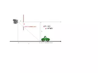
Detector 8 & 16 CENTER OF 805MHz cavity TO DETECTOR 16 (NaI crystal): 6629mm CENTER OF 805MHz cavity TO DETECTOR 8 (small scintillator paddle): 5994MM RD46 CHIPMUNK DETECTOR IS AT the DOWNSTREAM BEHIND THE 805 MHz CAVITY Det. 16 NaI crystal Det. 8: small Scintillator paddle DOWNSTREAM NFMCC08, 03/17/2008, Fermilab
X-ray background measurements Recording x-ray events for 1000 rf pulses at 10Hz rep. rate, i.e., 100sec. Creating electronic gates to record x-ray events in the fill, flattop and decay part of RF envelope for #16, record the total number of events during the whole RF duration for the rest of the detectors. RF pulse length ~ 20-μs Procedures • Achieve the maximal accelerating gradient at different magnetic fields • Due to change of geometry structure, the resonance frequency of the 805MHz cavity with button is shifted to ~810MHz • The modulator frequency and amplification needs to be adjusted to obtain the desired RF amplitude and waveform • Once the input RF signal is tripped off by the bad vacuum, modulator error, etc; or the radiation level and/or the vacuum level seems abnormally high; the RF amplitude needs to be decreased to regain the stable running with the desired radiation/vacuum level. After the cavity has been running stably for a while (5-10 minutes), we can then push up the RF amplitude a little bit higher. By repeating this method, we can achieve the maximal accelerating gradient without damage to the button • We measured the maximal accelerating gradient at different magnetic fields up to 4T in every 0.25T NFMCC08, 03/17/2008, Fermilab
Measurements and data • In the 1st TiN_Cu button test, we observed almost 80% of TiN coating was peeled off after the test and we don’t exactly know how and when. Therefore, the data of it may not be accurate. Cu TiN coating NFMCC08, 03/17/2008, Fermilab
Maximal achievable accelerating gradient at different magnetic field measured in 2007 • The gradient here is the local gradient on the button surface. In experiment, we measured the average gradient on the pillbox wall. By multiplying it with an enhancement factor of 1.7, we have the gradient on the button surface • The yellow curve of TiN_Cu is not as stable as the rests, it may be because of the loss of TiN coating in the test process • The field gradient on the TiN_Cu button seems improved compared to the light blueCopperpillbox cavity curve • The redMo button curve is almost always above the deep blueW button curve, therefore it seems like Mo is better than W NFMCC08, 03/17/2008, Fermilab
New data of TiN_Cu #2, 2008, (undone yet) • Just recently, we started to test a new TiN_Cu button which was applied a new coating tech. by LBL. Compared to the last time, we didn’t push the gradient very hard so that the surface damage could be diminished. • The RED curve corresponds to the new button. It looks much more stable than the YELLOWcurve and isexpected to be performing better at higher magnetic field according to its tendency NFMCC08, 03/17/2008, Fermilab
Where x-ray comes from? • High peak RF fields in the cavity may induce • Multipactoring • Field emission • Sparking • … • As a result: • Electrons, ions, …, stripped from cavity walls hit surfaces inside cavity x-rays NFMCC08, 03/17/2008, Fermilab
X-Ray background: #8, #16 raw data at B=1T (2007) • Red curves are TiN_Cu, yellow curves are Mo, Blue curves are W • The X-ray radiation level seems no much difference for these 3 buttons at fixed magnetic field • Note: compared to the raw data, the cosmic background is negligible Det. 16 curves Det. 8 curves NFMCC08, 03/17/2008, Fermilab
X-Ray background: #8, #16 raw data at E=19.58MV/m (2007) • Red curves are TiN_Cu, yellow curves are Mo, Blue curves are W • Again, The X-ray radiation level seems no much difference for these 3 buttons at fixed accelerating gradient Det. 16 curves Det. 8 curves NFMCC08, 03/17/2008, Fermilab
X-Ray background: detector raw data of TiN_Cu button as B=0 Saturation region • Before saturation, all the curves follow exponential growth, which obeys Fowler-Nordheim field emission rule. NFMCC08, 03/17/2008, Fermilab
RD46 chipmunk radiation detector readouts (mRad/Hr) for TiN_Mo button • Very sensitive to accelerating gradient, ~E14 . A small variation of accelerating gradient can introduce large change of radiation background NFMCC08, 03/17/2008, Fermilab
Summary and future plan • Experimental studies of different button materials in 805-MHz cavity have been carried out at MTA. • Experiment setup and diagnostics worked well, and ready for more extensive studies • Grave loss of TiN coating on the first TiN_Cu button. We are working more carefully to avoid it: e.g., push up the accelerating gradient slower and more cautiously to avoid quick and big spark; reduce the gradient immediately while big spark appears, etc. • Mo seems performing better than W • X-ray background radiation obeys Fowler-Nordheim rule before saturation. • Future plan: finish the 2nd TiN_Cu button test, and start the last TiN_Cu button coated by LBL ASAP; compare the data of all the buttons to see differences and/or improvements NFMCC08, 03/17/2008, Fermilab