Download
1 / 22
390 likes | 880 Views
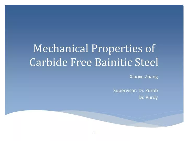
Mechanical Properties of Carbide Free Bainitic Steel. Xiaoxu Zhang Supervisor: Dr. Zurob Dr. Purdy. Motivation. CFB. Carbide Free Bainitic Steel. Microstructure. Caballero 2004. Complex microstructure : bainitic ferrite + retained austenite + martensite Nano-scale microstructure

E N D
Mechanical Properties of Carbide Free Bainitic Steel Xiaoxu Zhang Supervisor: Dr. Zurob Dr. Purdy
Carbide Free Bainitic Steel Microstructure Caballero 2004 • Complex microstructure: bainitic ferrite + retained austenite + martensite • Nano-scale microstructure • Bainitic ferrite: 200-400 nm thick • Retained austenite: 20–40 nm thick • Retained austenite: carbon partitioning to austenite; austenite film trapped in between bainitic ferrite and stabilized at room temperature • Silicon (~1.5%) suppress carbide formation
Carbide Free Bainitic Steel Heat Treatment Process Design Fe-0.4%C-2.8%Mn-1.8%Si (mass%) A3 Bainite 80% 30%
Optical Microstructure 300CX30mins 300CX60mins 300CX90mins 300CX120mins
Comparison between CFB and DP steel CFB Scale Effect DP Bouaziz 2012 Caballero 2012 UTS and UEI of DP and CFB steel with same carbon content
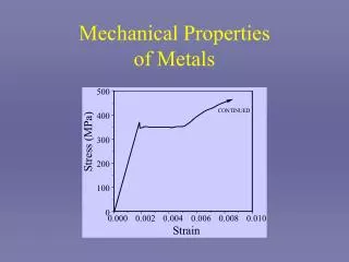
Work Hardening Considere criterion: dσ/dε=σT σT Necking point dσT/dεT σT σ σ Necking point UTS dσT/dεT dσT/dεT CFB dσT/dεT DP dσT/dεT εT UEI σ-σY
Work-Hardening Behaviour 30 minutes 60 minutes 90 minutes 120 minutes ϴII =E/50
MasingModel n σy 14 element Masing Model: elements yield at different stresses Complex microstructure: mixture of elements with wide range of yield strength Elasto-plastic transition Different stage of deformation of each element Internal stress developed during unloading and reversed loading
Elasto-Plastic Transition ϴII =E/50 dσ/dε = f ϴII + (1-f) E the calculated fraction of the material which has yielded (f) for specimen heat at 300C for 120mins Probability Density distribution of the yielded material for specimen heat at 300C for 120mins
Bauschinger Test specimen heated at 300C for 120mins
Stability of Retained Austenite TRIP effect does not play a main role in work hardening of carbide free bainitic steel. Wang, FGM McMaster, 2010 TEM image for 90 minutes at 300oC and cold-rolled to an equivalent strain of 0.3.
Macrostructure-banding • Banding structure due to Mn segregation during casting • Bands of martensite with band width of 200um • Increase hardenability (decrease potential of pearlite formation) • Affect reproducibility of mechanical properties and transformation kinetics • Homogenization procedure is not applicable to industrial production Banding Structure Elements of Metallurgy and Engineering Alloys
Acknowledgement Natural Science and Engineering Research Council of Canada ArcelorMittal Dr. Zurob Dr. Purdy Dr. Embury Dr. Brechet Dr. Olivier Xiang Wang Jim, Doug, Xiaogang
KocksMecking Model ϴ Stage II Stage III ϴII =E/50 σ