Download
1 / 27
270 likes | 334 Views
Data acquisition system for a proton imaging apparatus.

E N D
Data acquisition system for a proton imaging apparatus V.Sipalaa,b, D.LoPrestia,b, N.Randazzob, M.Bruzzid,e, D.Menichellie,d, C.Civininid, M. Brianzid, M.Bucciolinic,d, C.Talamontic,d, M.Tesie,L.Marrazzoc,d, L.Capinerif, S.Valentinid,f G.Cuttoneg, G.A.P.Cirroneg, G.Candianog, E.Mazzagliag a) Dipartimento di Fisica, Università degli Studi di Catania b) INFN, sezione di Catania c) Dipartimento di Fisiopatologia Clinica, Università degli Studi di Firenze d) INFN, sezione di Firenze e) Dipartimento di Energetica, Università degli Studi di Firenze f) Dipartimento di Elettronica e Telecomunicazioni, Università degli Studi di Firenze g) Laboratori Nazionali del Sud-INFN, Catania.
Outline • Proton therapy and proton imaging • Proton imaging apparatus • Data acquisition system • Tracker • Single module architecture • Detector • VLSI front-end • Calorimeter • Crystal YAG:Ce • Electronic readout • Trigger system • First results with proton beam • Conclusions valeria.sipala@ct.infn.it
Proton therapy The proton therapy is a good clinical treatment for cancer as it permits to obtain a dose distribution extremely conform to the target volume. The Bragg peak shape ensures that healthy tissues in front of and beyond the tumor are not damaged. Through the weighted superposition of proton beams of different energies it is possible to deposit a homogenous dose in the target region using only a single proton beam direction. (Spread Out Bragg Peak -SOBP). valeria.sipala@ct.infn.it
proton Computed Tomography – pCTProton imaging Main issues in the quality of treatment in proton therapy are: • Patient positioning • Dose planning Actually X-rays radiography and X-CT are used but… photons and protons are a different interaction with the matter By the pCT it’s possible to obtain: • Directly measurements of the stopping power distribution using the same therapeutic beam • In a single phase the patient positioning and the treatment valeria.sipala@ct.infn.it
pCT parameters Critical parameters: • Proton beam rate Data acquisition system • Spatial resolution Multiple Coulomb Scattering valeria.sipala@ct.infn.it
L’ L’’ L C A B Reconstruct principle: Most Likely Path A: Only entry position & direction known: straight line L B: Entry position & direction + exit position known: straight line L’ C: Entry position & direction + exit position & direction known: curved path L’’, “banana-shaped”, narrow confidence limits valeria.sipala@ct.infn.it
Calorimeter Silicon Telescope Silicon Telescope proton Computed Tomography concept • Reveal the trace of the single proton using a silicon telescope • Measure the residual energy of the proton using a calorimeter • Reconstruct the most likely path of the single proton • Reconstruct the imagine valeria.sipala@ct.infn.it
Validation of semi-analytical algorithms with pre-existing data Data acquired at LLUMC Proton beam 201MeV Silicon tracker UCSC CsI(Tl) calorimeter Acquired on p5 Reconstructed on p5 Acquired on p4 C. Talamonti et al., "Proton Radiography for clinical applications," NIM A, in press. valeria.sipala@ct.infn.it
Proton imaging apparatusFirst step in the realization of pCT device • 4 x-y TRACKER MODULES • 1 CALORIMETER Entry and Exit position and direction Residual Energy valeria.sipala@ct.infn.it
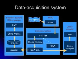
Data acquisition system valeria.sipala@ct.infn.it
Detector board with a detector and 8 chips containing the electronic front-end. Single TrackerModule Front-end board Detector location Digital board 1 x-y plane consists of 2 single tracker modules valeria.sipala@ct.infn.it
Tracker module architecture To achieve a read-out rate of 1MHz a fully parallel digital strip readout system has been developed Eight 32-channel VLSI front-end chips acquire the detector signals and sends data in parallel to an FPGA (Xlinx Spartan-3AN) which performs zero suppression and moves data to a buffer memory (~5x10⁵ events). An Ethernet commercial module is used both for data transfer to the central acquisition PC and to control the tracker module DAQ parameters 14/3/2009 valeria.sipala@ct.infn.it
53 mm x 53 mm n-type substrate with p-type implants 200 μm thickness 256 strips, each 57 μm thick 200 μm pitch Integrated resistance for bias 1.5MOhm DC PAD AC PAD Guard ring Substrate bias PAD Bias ring Detector Description valeria.sipala@ct.infn.it
AMS 0.35u CMOS Technologie 1.6 mm x 6 mm 32 channels Power dissipation = 14,5 mW @ chan Vcc = +3.3 V Single channel OUT Charge Sensitive Amplifier Differentiator (high pass) Integrator (low pass) Comparator Buffer External threshold voltage Single strip VLSI front-end description valeria.sipala@ct.infn.it
Calorimeter • 4 YAG:Ce scintillating crystals Each crystal 30 x 30 mm2 x 100mm • 4 Photodiode 18 mm x 18 mm • 4 commercial front-end(Charge Sensitive Amplifier & shaper ) Charge spectrum @100MeV valeria.sipala@ct.infn.it
Calorimeter readout & Trigger generator board valeria.sipala@ct.infn.it
Tracker module test • First results of the beam test at Laboratori Nazionali del Sud with 62MeV protons • New calibration • Test with beta source valeria.sipala@ct.infn.it
Tracker module: 62MeV proton beam at Laboratori Nazionali del Sud (LNS) A threshold voltage value for all chips Front-end board and digital board : beam profile Time Over Threshold for different threshold voltage valeria.sipala@ct.infn.it
Single tracker module:New calibration with a threshold voltage value for each chip Efficiency of all channels vs input charge for fixed threshold voltage: ΔVth=0 Efficiency of all channels vs threshold voltage for fixed input signal: Q= 5MIP valeria.sipala@ct.infn.it
Single tracker module:New calibration with a threshold voltage value for each chip • T(Q) calibration curves: Duration pulse vs input equivalent charge valeria.sipala@ct.infn.it
Single tracker module: Test with beta source 90Sr • Acquisition rate = 20kHz • Total counts =100000 events valeria.sipala@ct.infn.it
Calorimeter test • Linearity study • Homogeneity study • New electronic readout valeria.sipala@ct.infn.it
Calorimeter: beam test -Loma Linda Medical Center Charge spectrum at different proton energies valeria.sipala@ct.infn.it
Calorimeter: beam test -Loma Linda Medical Center Linearity ( 30-200MeV energy proton range ) valeria.sipala@ct.infn.it
60mm 60mm Calorimeter: beam test -Loma Linda Medical CenterSingle crystal homogeneity study The tracker area has been divided into 30x30 squares (area = 2x2mm2). For each square the charge spectrum has been made. This is the map of the charge spectrum peak value valeria.sipala@ct.infn.it
Yesterday CR110 + CR220-3us Today Calorimeter: New electronic readout Bassini, Boiano and Pullia IEEE TNS, VOL. 49, NO. 5, OCTOBER 2002 Test with YAG:Ce in October ‘09 Low acquisition rate High acquisition rate valeria.sipala@ct.infn.it
Conclusions A proton imaging device is being built by the Italian collaboration • Tracker • Single module: assembled and tested at LNS with 62MeV proton beam • Calorimeter • YAG calorimeter: completely characterized at LLMC with 30-200MeV proton beam • Front-end electronics: prototype exists (commercial parts) • Trigger generator assembled Future plans • Calorimeter with new front-end (higher rate): to be tested with proton beam (by the end of 2009) • Two tracker modules (one x-y plan) and the calorimeter: to be tested with proton beam (by the end of 2009) • Complete device built (by the end of 2010) valeria.sipala@ct.infn.it