Download

1 / 26
260 likes | 389 Views
This guide provides an overview of sensors and microcontrollers, essential for robotics education. Learn about digital IR sensors like the TSOP 1738, which detects infrared signals at a pulse rate of 38 KHz, and analog sensors that measure reflected IR light. Explore the role of microcontrollers, including the Atmega series, which act as the brains of robots. Understand the programming aspects, including the generation of hex files and the interfacing of various components. Ideal for students and educators in robotics and electronics.

E N D
Schools of Robotics . • Mechanical Design • Electronics • Programming
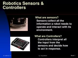
What Are sensors ? • Any device that converts a change in physical quantity into electrical signals.
Tsop 1738 • It is a Digital IR Sensor. • Works for IR pulse rate 38 KHz. • Pulse rate set by microcontroller. • Accurately distinguish between two colors. • Outputs – 0 and 5 Volts.
Analog IR sensor • Measures amount of reflected IR light • Outputs in the range of 0V to 5V • Hence, called Analog Sensor
Light Dependent resistor • Made of calcium Sulphate • Act like open circuit in absence of light • In light, resistance drops from 1 M ohms to10 ohms • Popularly called LDRs.
7805 • Microcontrollers – 5V • Motors – 12V • Converts 8V to 12V into 5V • Rest lost as heat • Current Rating - 0.5 A
Integrated Circuits • Programmable – Simplest form of microcontroller • Non – Programmable • E.g. 555, AND gate, OR gate, Mux, Inverters, etc.
Micro-Controllers • A micro controller is the brain of the robot. • Logic tables relating Input and Output can be defined by you. • Many other useful features built into the IC itself.
Working • Consists of CPU interfaced with RAM and Flash Memory. • Flash memory is Programmable • CPU accesses information from RAM, which gets it from the flash memory
Programming • Understands only binary language • Code written in C • Used to generate a .hex file • Transfer the .hex file using a programmer
I/O Pins • DDRX Registers • PORTX Registers • PINX Registers
Timers • Timer 0 – 8 bit ( OC0 at PB3) • Timer 1 – 16 bit ( 2 parts, OC1A at PD5 and OC1B at PD4) • Timer 2, 8 bit (OC2 at PD7) • System Clock (fs) • Timer Clock