Download
1 / 38
380 likes | 585 Views
OncoRay – National Center for Radiation Research in Oncology, Dresden. Contributions of TUD to WP2: Simulations and Image Reconstruction for in-beam PET WP2 Meeting, Valencia, 10 th December 2013. Heide Rohling , Wolfgang Enghardt OncoRay, TU Dresden

E N D
OncoRay – National Center forRadiation Research in Oncology, Dresden Contributions of TUD to WP2:Simulations and Image Reconstruction for in-beam PETWP2 Meeting, Valencia, 10th December 2013 Heide Rohling, Wolfgang Enghardt OncoRay, TU Dresden Fine Fiedler, Helmholtz-Zentrum Dresden-Rossendorf
Workflow of Simulation and Reconstruction Patient Data Simulated Annihilation Points Simulation of Detector Response (GATE) Coincidence Events (simulated time + spatial blurring) Reconstruction: Direct TOF or TOF-MLEM Simulated annihilation points Optimized RPC-based scanner Reconstructed image
Patient data Pilote study at GSI 1997-2008: patient treatment with 12C Patient1Patient2
Patient data Simulation of the annihilation point distributions (Pönisch et al. 2004) Relevant Nuclides: 15O, 14O, 13N, 11C, 10C Extraction pause (-40 %) Number of Annihilations: 3.6 · 105 (Patient1) 2.6 · 106 (Patient2)
Patient data Patient1 Simulated annihilation points Patient2
Patient data as a source in GATE 6.1 (1) Voxelized source in GATE: Annihilation map: one entry corresponds to 1 Bq Scaled to 180 s (irradiation time) in rangetranslator-files Size: 287 287 267 mm³ and 310 310 306 mm³ Voxelsize: 1 1 1 mm³ (2) Voxelized phantom in GATE: Original CT-scan HU-units included in GATE as AnalyzeTM-file (ImageNestedParametrisedVolume) Conversion to material by means of tables
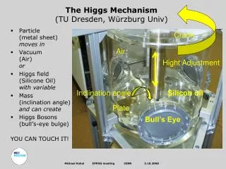
Extended/optimized detectors under consideration See also Torres-Espellardo et al. to be submitted to Phys. Med. Biol.
Annihilation points: Patient1: 3.6 · 105, Patient2: 2.6 · 106 Sensitivity for patient sources GeminiTF: real readout cannot be modelled with GATE (in simulation: each crystal) Surti et al. 2007: 6.6 cps/kBq obtained by the GeminiTF => 4 % coincidence efficiency can be assumed for the extended partial ring Gemini-based scanner => The rate of coincidences increases to 14800 and 108000 for Patient1 and 2, respectively
Further optimization of RPC-based scanner geometry Increase of coincidences: 30 % (point source in center)
Reconstructed Images: Patient1 RPC vs. Gemini-based PET-scanner: Patient1 LYSO: 200 ps FWHM LYSO: 400 ps FWHM LYSO: 600 ps FWHM Original annihilation data
Reconstructed Images: Patient1 RPC vs. Gemini-based PET-scanner: Patient1 LYSO: 200 ps FWHM LYSO: 400 ps FWHM LYSO: 600 ps FWHM Original annihilation data RPC: 50 ps FWHM RPC: 100 ps FWHM RPC: 200 ps FWHM
Reconstructed Images: Patient2 LYSO: 400 ps FWHM LYSO: 600 ps FWHM LYSO: 200 ps FWHM Original annihilation data
Reconstructed Images: Patient2 LYSO: 400 ps FWHM LYSO: 600 ps FWHM LYSO: 200 ps FWHM Original annihilation data RPC: 50 ps FWHM RPC: 200 ps FWHM RPC: 100 ps FWHM
Performed Reconstruction TOF-MLEM (Shakirin 2009) - on-the flight system matrix - ray tracing with 10 lines of response Direct TOF (Crespo et al. 2007) - suitable if resolution better than 200 ps FWHM - also 10 lines of response - 1 iteration How to define the lines of response: (1) Crystal-based scanner: endpoints distributed uniformly over surface of corresponding crystals (2) RPC-based scanner: endpoints distributed according to the spatial resolution of the RPC (Gaussian) around the point of interaction
Optimization of reconstruction algorithm State-of-the art: TOF-MLEM Parameters to adjust: Voxelsize (2 2 2 mm3) Number of iterations: contrast vs. noise (Surti et al. 2006, Lois et al. 2010) TOF-kernel (Daube-Witherspoon et al. IEEE, 2008) TOF-MLEM vs. Direct TOF Evaluation of image quality RMSE SNR Tools dedicated to detect range deviations in PT-PET patient data (e.g. YAPET (WP5))
Reconstructed Images: Direct TOF vs. TOF MLEM RPC, Patient1 50 ps FWHM 100 ps FWHM 200 ps FWHM Direct TOF Original annihilation data
Reconstructed Images: Direct TOF vs. TOF MLEM RPC, Patient1 50 ps FWHM 100 ps FWHM 200 ps FWHM Direct TOF Original annihilation data TOF MLEM 200 ps FWHM 50 ps FWHM 100 ps FWHM
Reconstructed Images: Direct TOF vs. TOF MLEM Direct TOF RPC, Patient1 Original annihilation data TOF MLEM No TOF MLEM 50 ps FWHM 100 ps FWHM 200 ps FWHM
Reconstructed Images: Direct TOF vs. TOF MLEM Direct TOF RPC, Patient1 Original annihilation data TOF MLEM Elongation Artifacts No TOF MLEM 50 ps FWHM 100 ps FWHM 200 ps FWHM
Reconstructed Images: Direct TOF vs. TOF MLEM Gemini-based scanner, Patient1 Direct TOF Original annihilation data 200 ps FWHM 400 ps FWHM 600 ps FWHM
Reconstructed Images: Direct TOF vs. TOF MLEM Gemini-based scanner, Patient1 Direct TOF Original annihilation data TOF MLEM 200 ps FWHM 400 ps FWHM 600 ps FWHM
Reconstructed Images: Direct TOF vs. TOF MLEM Gemini-based scanner, Patient1 Direct TOF Original annihilation data TOF MLEM No TOF MLEM 200 ps FWHM 400 ps FWHM 600 ps FWHM
Reconstructed Images: Direct TOF vs. TOF MLEM: RPC, Patient2 Direct TOF 200 ps FWHM Original annihilation data 50 ps FWHM 100 ps FWHM
Reconstructed Images: Direct TOF vs. TOF MLEM: RPC, Patient2 Direct TOF Original annihilation data TOF MLEM 100 ps FWHM 200 ps FWHM 50 ps FWHM
Reconstructed Images: Direct TOF vs. TOF MLEM: RPC, Patient2 Direct TOF Original annihilation data TOF MLEM 100 ps FWHM 200 ps FWHM 50 ps FWHM No TOF MLEM
Reconstructed Images: Direct TOF vs. TOF MLEM: RPC, Patient2 Direct TOF Original annihilation data TOF MLEM Elongation Artifacts 100 ps FWHM 200 ps FWHM 50 ps FWHM No TOF MLEM
Reconstructed Images: Direct TOF vs. TOF MLEM: RPC, Patient2 Direct TOF Original annihilation data TOF MLEM Elongation Artifacts 100 ps FWHM 200 ps FWHM 50 ps FWHM No TOF MLEM
Reconstructed Images: Direct TOF vs. TOF MLEM: Gemini-based, Patient2 Direct TOF Original annihilation data 200 ps FWHM 400 ps FWHM 600 ps FWHM
Reconstructed Images: Direct TOF vs. TOF MLEM: Gemini-based, Patient2 Direct TOF TOF MLEM Original annihilation data 600 ps FWHM 400 ps FWHM 200 ps FWHM
Reconstructed Images: Direct TOF vs. TOF MLEM: Gemini-based, Patient2 Direct TOF TOF MLEM Original annihilation data No TOF MLEM 600 ps FWHM 400 ps FWHM 200 ps FWHM
Influence of TOF information on convergence RPC: impact of TOF more evident
Detection of range deviations with YAPET (WP5) Activity / a.u. Activity / a.u. Distal edge Beam direction Beam direction 1D profile in beam directionannihilation mapvs.Gemini (200 ps FWHM) 1-D profile in beam directionannihilation mapvs.RPC(100 ps FWHM)
Detection of range deviations with YAPET (WP5) Work in progress: Variation of energy => Variation of range (± 2mm, …, ± 10 mm) => range deviation detectable?
. Thank you for your attention!
Sensitivity of the GeminiTF-based scanner Surti et al. 2007: 6.6 cps/kBq obtained by the GeminiTF for a 70 cm line source and a plastic cylinder The axial dimension is 18 cm (a longer source as no effects) => Reduction of emissions : factor 18/70 Adjustment to extended scanner: 40/18 Considering of partial ring geometry: factor 20/28 This is 6.6/1000/(18/70)*(40/18)*(20/28) = 4%
NEMA-like Phantom Shape: hollow cylinder Material: water Height: 9 cm Radius: 9 cm, inner radius: 2.5 cm Hot spheres with radius: 5 mm, 6.5 mm, 8.5 mm, 11 mm Cold spheres with radius: 14 mm, 18.5 mm Acitivity: 4:1:0 NEMA-Phantom: schematic view Georgy Shakirin Thesis 2009