Download
1 / 31
310 likes | 471 Views
RF performance and operational issues. The LHC RF team reported by A. Butterworth Special thanks: L. Arnaudon, E. Ciapala, Ph. Baudrenghien, O. Brunner, W. Hofle, J. Molendijk. Outline. Operational difficulties Klystron collector power Spurious hardware trips Switch-on problems

E N D
RF performance and operational issues The LHC RF team reported by A. Butterworth Special thanks: L. Arnaudon, E. Ciapala, Ph. Baudrenghien, O. Brunner, W. Hofle, J. Molendijk
Outline • Operational difficulties • Klystron collector power • Spurious hardware trips • Switch-on problems • Controls & software • (De-)Synchronisation • RF readiness for unsafe beam • interlocks • Transverse damper readiness • cable issues • noise • Summary & conclusions
Klystron collector power • Nominal scheme for cavity operation: Injection: 1MV/cavity, Q= 20000, 135 kW Physics: 2MV/cavity, Q= 60000, 185 kW • Q is changed before acceleration using moveable cavity power coupler • Klystron DC power ≈ 500 kW (58 kV x 9A) • But: in 2008/9, decided to work with fixed Q = 60000 • 1MV requires only 45 kW Input cavity Output cavity RF In RF Out Pcollector = PDC – PRFout Pcollector close to rated maximum
Klystron collector power Collector opened 15/01/10 Potential concern - under investigation.
Klystron collector power • Mitigation: reduce collector power: • fewer cavities with higher voltage per cavity • higher RF power per klystron reduced collector power (below 450 kW) • 4 cavities @ 2 MV, many RF trips • cavities had de-conditioned during 2 weeks of running at injection level • eventually +/- reliable with 5 cavities @ 1.6 MV • Other measures: • Automatically switch power system to READY when RF OFF • reduced current, Pcollector ≈ 100kW
Choices for 2010 running • Reduce number of cavities • no limit in 2010 on beam current from impedance of unused cavities (detuned by 100 kHz) • cannot reach nominal 16 MV per beam in physics with Q=60000 • go to higher Q ? • Work at lower DC power • no headroom for feedback at 2MV during physics • reduce cavity voltage? • Commission nominal scheme: move coupler to change Q after injection • more time needed before startup to fine-tune loop parameters at different Q values • (2 weeks with cavities cold) only long-term solution for higher intensities
Hardware issues: spurious interlocks • “Slow” interlocks via PLCs • waveguide/coupler blowers • water flows ... • threshold & detection time adjustable in PLC • RF reflected power interlocks (wattcher) • changed integration time • slowed rf voltage ramp-up rate at switch-on • also helps cryo stability • Cryogenics • He pressure interlocks due to de-conditioning
Thyratron (crowbar) spurious triggers • Many crowbars when starting/raising HV Reduce HV power converter ramp rate to klystrons • Crowbar triggers do not come from klystrons • 1 coil to fire thyratron • 1 coil to generate power converter interlock • 1 coil for each klystron: used for interlock diagnostics • no triggers seen on klystron channels
Thyratron (crowbar) spurious triggers • Thyratron heater adjustment • 4 heaters must be regulated < 0.05V in 4.5V • drifts cause auto-triggers, e.g. when ramping HV re-check adjustment and observe • During conditioning in LHC and operation in SM18 there were almost no crowbars • difference in LHC is the earth system for the HV bunkers • earth connected in RB (far from bunkers) • sensitive to noise when machine is running • PC trips trigger crowbar investigate: measure earth noise with scope
Power system switch-on problems • Crowbars • repeated HV trips • power converter post-mortem blocks PC comms for ~1 minute • RF application should inform of this • Wrong manipulation: 18kV switched on with PC on (more than once) • broke some 5V power supplies in HV bunker • could have caused more damage... • a safety interlock on 18kV has been requested from EN/EL • Alarm diagnostics • sometimes fails due to bug in FESA class, will be rectified before startup • alarms are yellow (should be red)... • Software issues...
Application blocking & FEC crashes • FESA classes running on cfc-ccr-cgplrf • many subscriptions: machine starts to overload • notification message queue between FESA RT and Server becomes full • FESA surveillance mechanism notifies server via signal • signal caught by any random thread • FESA crash... application “blocks” • only hope of restart is to kill all clients and reboot Fixed display RF application RF application RF application Fixed display ... CMW subscriptions cfc-ccr-cgplrf Server process FESA shared server Notification message queues Real time processes ACSLine ACSLinePLC ALLLine ... Bug found, fixed & tested (thanks to FESA team)
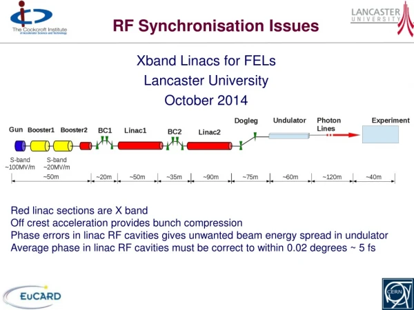
Synchronisation problems • Coarse frequency program reference for ring 2 • want to use ring 1 reference when rings locked together • using wrong reference can make synchro loop unlock on a large trim FGC and sequencer mods to allow use of ring1 reference for both rings • Phase loop problem with beam & RF off • at injection gives random phase -> phase loop kicks synchro loop out of sync • same when switching RF off with beam (e.g. for debunching) • added threshold in firmware -> switching RF off disables phase loop • Beam control Clock generators • resync of 40MHz sampling clock had been forgotten from synchro initialisation sequence • used for sampling in beam phase module • come up with random phase if not properly resynced added resync of 40 MHz to frev • Installed diagnostics (TDC measurements) • on BC1 crates (frev master vsfrevprog) • in Synchro system between frevprog 1 and 2 (ns) Synchro loop error (blue) during 855Hz trim Resynchronisation Injection Synchro loop unlocking at injection
Readiness for unsafe beam • No beam interlocks on RF voltage or RF trips currently connected • at 1/2 nominal intensity, beam can survive 1 cavity trip • ultimately will need interlock on RF off for each cavity controller • currently not implemented • but for now, add an interlock on the cavity voltage sum: beam dump if below threshold • Frequency interlocks • coarse interlock on 40MHz (corresponds to +/- 10 kHz on RF) • fine interlock +/- 200Hz on RF: • measured behind distribution in UX45 every 50ms • implemented but not enabled (or tested) yet • test before startup, and enable for unsafe beam (maskable) • ring1/ring2 inversion check before each fill? • software interlock on cavities remote/local clock status? • Synchronisation • de-synchronisation frev master/prog during injection will make SPS inject in wrong bucket (possible over-injection) • should interlock the TDC measurement?
Low Level RF for 2010 • Cavity controller • variable coupler: change of Q • put 1-turn feedback into operation • further impedance reduction for increased intensity • minor impact on operation • Injection transient phase/synchro errors • fixed display done • automatic adjustment procedure for injection phase needs to be developed • reduce need for longitudinal feedback • Longitudinal feedback (2nd half 2010) • bunch by bunch damping of injection errors • needs firmware development • fibre cabling in progress • will need some (short) accesses after startup for equipment installation • Emittanceblowup by controlled noise • hardware/firmware in place • software in progress • MDs needed
ADT: Readiness for 2010 running • Power system: • more than 2000 hours operating time accumulated • Damper Lowlevel: • hardware completed and available in 2009 • feedback not yet closed (no time allocated for commissioning) • Controls • application software tested and used operationally • Lowlevel software (function generators, expert software, abort gap cleaning) tested in dry-runs and during beam • Abort gap cleaning tested with beam • software and firmware to generate the cleaning pulses worked very well • data analysis ongoing • optimization of cleaning pulse in order not to touch beam outside abort gap is necessary • Major issues encountered • impulse response of cable from pickups (ripple) • reduction of beam lifetime by unwanted excitation through damper
Issue with long 7/8” cables from pick-ups • 7/8” Flexwell cable is known to have some ripple in the impulse response due to the corrugation • The 16 cables for the ADT pick‐up cables from SR4 to the tunnel have a larger than expected variation of the ripple from cable to cable when excited by the bunch passing the pick‐up Signal from single bunch as measured on the surface; the large ripple is due to a periodic perturbation on the cable Good cable for comparison
Issue with long 7/8” cables from pick-ups Periodic perturbation visible in reflectometry, compatible with pitch of ladder (attachment every 60 cm = 2 x 30 cm) Zoom into the time domain S11 data of damaged cable Two cables being replaced during the technical stop reconsider pick-up signal processing if necessary (all cables show some signs of this problem)
Tests done 7.12.2009 in UX45 • Measured noise injected from the BI excitation input
Tune measurement (BBQ), BI input off, ADT level 3 (blue) on, versus level 2 (red) No influence on life-time 8 kHz + ~50 Hz lines
Disappearance of 8 kHz line in damper spectrum when UPS’ in UX45 and SR4 are bypassed line at 16 kHz probably caused by another ground loop involving other UPS or equipment
Reduction of damper noise at 8 kHz by common mode choke in UX45 choke will be improved, measurement shows that problem is a ground loop
Summary: RF • Power system: • minor hardware problems understood and addressed • possible concern over klystron collectors • operating mode needs to be defined • time needed to commission variable cavity Q • Controls & software: • major operational problems solved • Low level & synchro: • various causes for synchronisation problems understood and resolved • Readiness for unsafe beam: • addition of interlocks on cavity sum, frequency and synchro • To do... • Q change, 1T feedback, longitudinal feedback, emittanceblowup...
Summary: ADT • Commissioning with beam started, need dedicated time 2010 for commissioning ! • Noise spectra need attention, remove ground loops by common mode chokes • improved ground between surface and underground areas necessary ? • Two pick-up cables (7/8”) will be replaced during the technical stop, • performance for multi-bunch operation to be checked (residual ripple from cable) • Abort gap cleaning promising, but pulse shape optimization
Details of spectrum; 8 kHz + lines spaced 100 Hz 8 kHz 7.9 kHz 8.1 kHz
Spectrum of 230 V perturbation in a rack supplied by UPS; main contributions: < 2 kHz, 8 kHz, 16 kHz one phase in damper racks (SR4) to neutral < 2 kHz 8 kHz 16 kHz
Issue with long 7/8” cables from pick-ups Seems to be due to the way the cables are attached in the vertical part of the pit going down Reflection from cable in vertical part (in the pit) is high, periodic perturbation in frequency domain at approximately 200 MHz and 400 MHz (unfortunately)
Simplified synoptic of ADT (transverse damper) 8x per beam Currently disconnected 12.12.2009 HOM returns (32x)
Lifetime test 8.12.2009 damper level 3 on without BI signal 9:58 BI signal on (via switch and timing on RF side)
Lifetime test 5.12.2009 damper level 3 on with BI signal 17:45 damper level 3 off
Issue with noise on ADT kicker • Influence of damper level 3 (signal drive) on/off on beam lifetime and beam spectra observed (R. Steinhagen) • Investigations of noise spectra at damper equipment by RF group lead to the identification of different contributions: • Contribution from BI input signal for tune measurement, triangular shaped noise from 50 kHz to 250 kHz, fix is underway (filtering) for 2010 (BI group), 2009 fix was to attenuate the signal • 8 kHz (and multiples) identified to come from the UPS power supplies; confirmed in 2010 when SR4 and UX45 UPS’ where switched off (effectively by-passed) • Mechanism by which 8 kHz enters damper equipment is thought to be by ground loops (surface to under ground areas) • grounding scheme needs to be looked at, possibly improved ? • For 2010 a scheme to suppress the noise is to install common mode chokes at the input of the damper equipment in UX45 • 10 dB suppression shown already • chokes with more windings will be constructed for better suppression • if problem persists, another solution would be to move some equipment from the surface to UX45 considerable investment in time, only if really proven necessary