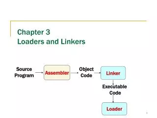
Linking Loader for SIC/XE Machine
Linking Loader for SIC/XE Machine. Beyond an Absolute Loader. Shortcoming of an absolute loader Programmer needs to specify the actual address at which it will be loaded into memory. It is difficult to run several programs concurrently, sharing memory between them.


Linking Loader for SIC/XE Machine
E N D
Presentation Transcript
Beyond an Absolute Loader • Shortcoming of an absolute loader • Programmer needs to specify the actual address at which it will be loaded into memory. • It is difficult to run several programs concurrently, sharing memory between them. • It is difficult to use subroutine libraries. • Solution: a more complex loader that provides • Program relocation • Program linking
Relocation • Loaders that allow for program relocation are called relocating or relative loaders. • Two methods for specifying relocation as part of the object program • Modification records • Suitable for a small number of relocations required when relative or immediate addressing modes are extensively used • Relocation bits • Suitable for a large number of relocations required when only direct addressing mode can be used in a machine with fixed instruction format (e.g., the standard SIC machine)
Example of a SIC/XE Program Only three addresses need to be relocated.
Object Program with Modification Records There is one modification record for each address need to be relocated.
Relocatable Program for SIC Fixed instruction format Direct addressing mode
Relocatable Program for SIC Fixed instruction format Direct addressing mode
Relocatable Program for SIC Direct addressing mode This program does not use relative addressing. Thus the addresses in all the instructions except RSUB must be modified. This would require 31 Modification records.
Relocation Bits • If there are many addresses needed to be modified, it is more efficient to use a relocation bit, instead of a Modification record, to specify every relocation. • When the instruction format is fixed as in SIC machine (one word per instruction), we can associate each instruction with a relocation bit. • Relocation bits can be gathered together into a bit mask to be stored in theText record. • If the relocation bit corresponding to a word of object code is set to 1, the program’s starting address will be added to this word when the program is relocated. … one word 1 1 1 1 1 1 0 0 Bit mask: F C
Object Program with Relocation Bit Mask Why a new record? Why a new record? • Relocation bits corresponding to unused words are set to 0. • The object code 040030 generated from the LDX instruction on line 210 begins a new Text record for proper alignment.
Program Linking • A program is a logical entity that combines all of the related control sections. • Control sections could be assembled together, or they could be assembled independently of one another. • Control sections are to be linked, relocated, and loaded by loaders. • External references among control sections can be assigned addresses after these control sections are loaded into memory by loaders.
Sample Program for Linking and Relocation • Each control section defines a list: • Control section A: LISTA --- ENDA • Control section B: LISTB --- ENDB • Control section C: LISTC --- ENDC • Each control section contains exactly the same set of references to these lists • REF1 through REF3: instruction operands • REF4 through REF8: values of data words • After these control sections are linked, relocated, and loaded, each of REF4 through REF8 should have resulted in the same value in each of the three control sections. (but not for REF1 through REF3, why?)
REF1 (LISTA) • Control section A • LISTA is defined within the control section. • Its address is immediately available using PC-relative addressing. • No modification for relocation or linking is necessary. • Control sections B and C • LISTA is an external reference. • Its address is not available thus an extended-format instruction with address field set to 00000 is used. • A modification record is inserted into the object code to instruct the loader to add the value of LISTA (once determined) to this address field.
REF2 (LISTB+4) • Control sections A and C • REF2 is an external reference (LISTB) plus a constant. • The address of LISTB is not available thus an extended-format instruction with address field set to 00004 is used. • A modification record is inserted into the object code to instruct the loader to add the value of LISTB (once determined) to this address field. • Control section B • LISTB is defined within the control section. • Its address is immediately available using PC-relative addressing. • No modification for relocation or linking is necessary.
REF3 (#ENDA-LISTA) • Control section A • ENDA and LISTA are defined within the control section. • The difference between ENDA and LISTA is immediately available. • No modification for relocation or linking is necessary. • Control sections B and C • ENDA and LISTA are external references. • The difference between them is not available thus an extended-format instruction with address field set to 00000 is used. • Two modification records are inserted into the object code • +ENDA • -LISTA
REF4 (ENDA-LISTA+LISTC) • Control section A • The values of ENDA and LISTA are known when assembled. Only the value of LISTC is unknown. • The address field is initialized as 000014 (ENDA-LISTA). • One Modification record is needed for LISTC: • +LISTC • Control section B • ENDA, LISTA, and LISTC are all unknown. • The address field is initialized as 000000. • Three Modification records are needed: • +ENDA • -LISTA • +LISTC • Control section C • LISTC is defined in this control section but ENDA and LISTA are unknown. • The address field is initialized as the relative address of LISTC ( 000030) • Three Modification records are needed: • +ENDA • -LISTA • +PROGC (for relocation)
Program in Memory after Linking and Loading Values of REF4, REF5, …, REF8 in three places are all the same. started at 4000 started at 4063 started at 40E2
Calculation of REF4 (ENDA-LISTA+LISTC) • Control section A • The address of REF4 is 4054 (4000 + 54) • The value of REF4 is: 000014 + 004112 = 004126 (initial value) (address of LISTC) • The address of LISTC is: 0040E2 + 000030 = 004112 (starting address of PROGC) (relative address of LISTC in PROGC) • Control section B • The address of REF4 is 40D3 (4063 + 70) • The value of REF4 is: 000000 + 004054 - 004040 + 004112 = 004126 (initial value) (address of ENDA) (address of LISTA) (address of LISTC)
References in Instruction Operands • For references that are instruction operands, the calculated values after loading do no always appear to be equal. • This is because there is an additional address calculation step involved for PC (or base) relative instructions. • In such cases, it is the target addresses that are the same. • For example, in control section A, the reference REF1 is a PC relative instruction with displacement 01D. When this instruction is executed, the PC contains the value 4023. Therefore the resulting address is 4040. In control section B, because direct addressing is used, 4040 (4000 + 40) is stored in the loaded program for REF1.
Implementation of An Assembler • Operation Code Table (OPTAB) • Symbol Table (SYMTAB) • Location Counter (LOCCTR) OPTAB Pass 1 Pass 2 Source program Intermediate file Object program SYMTAB LOCCTR
Load map Implementation of a Linking Loader • Two-pass process (similar to the Assembler): • Pass 1: assigns addresses to all external symbols • Pass 2: performs the actual loading, relocation, and linking Pass 1 Pass 2 Object programs (Control sections) memory ESTAB CSADDR
Data Structures • External Symbol Table (ESTAB) • For each external symbol, ESTAB stores • its name • its address • in which control section the symbol is defined • Hashed organization • Program Load Address (PROGADDR) • PROGADDR is the beginning address in memory where the linked program is to be loaded (supplied by OS). • Control Section Address (CSADDR) • CSADDR is the starting address assigned to the control section currently being scanned by the loader. • CSADDR is added to all relative addresses within the control section.
Algorithm (only Header and Define records are concerned)
Enhance the Algorithm • We can make the Assembler more efficient by storing search information in the intermediate file and avoiding the search of OPTAB in Pass 2. • We can make the linking loader algorithm more efficient by: • assigning a reference number to each external symbol referred to in a control section • Control section name: 01 • Other external reference symbols (stored in the Refer records): 02symname, 03symname, … • using this reference number (instead of the symbol name) in Modification records • avoiding multiple searches of ESTAB for the same symbol during the loading of a control section. • Search of ESTAB for each external symbol can be performed once and the result is stored in a table indexed by the reference number. • The values for code modification can then be obtained by simply indexing into the table.