Download
1 / 36
390 likes | 543 Views
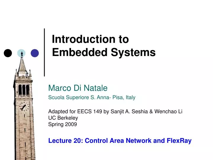
Introduction to Embedded Systems. Marco Di Natale Scuola Superiore S. Anna- Pisa, Italy Adapted for EECS 149 by Sanjit A. Seshia & Wenchao Li UC Berkeley Spring 2009. Lecture 20: Control Area Network and FlexRay. Today’s Cars. X-by-wire vs. conventional mechanical and hydraulic systems

E N D
Introduction toEmbedded Systems Marco Di Natale Scuola Superiore S. Anna- Pisa, Italy Adapted for EECS 149 by Sanjit A. Seshia & Wenchao Li UC Berkeley Spring 2009 Lecture 20: Control Area Network and FlexRay
Today’s Cars • X-by-wire vs. conventional mechanical and hydraulic systems • Basics: power locks/door/window/engine start • Sensors/Actuators: tire, powertrain, video, radar, and photoelectrics, etc. • Control/Safety: ABS, EBD/CBC, EBA/BAS/BA, ASR/TCS/TRC, ESP/DSC/VSC, etc. • Entertainment System • Auto-Park • DARPA’s Urban Challenge Image: General Motors
Today’s Cars • Number of Electronic Control Units (ECUs) in a car: • Low end: 30 ~ 50 (doors, roof, etc) • High end: 70~100 • Lines of code: ~100 million (Future: 200~300 million) • The radio and navigation system in the current S-class Mercedes-Benz requires over 20 million lines of code alone and that the car contains nearly as many ECUs as the new Airbus A380 (excluding the plane’s in-flight entertainment system). • Cost of electronics/software: 35% ~ 40% in premium cars (for hybrid it is even higher!) • How can we ensure timely and reliable communication via the “wires”? [http://www.spectrum.ieee.org/feb09/7649]
CAN bus CAN = Controller Area Network • Publicly available communications standard [1] http://www.semiconductors.bosch.de/pdf/can2spec.pdf Serial data bus developed by Bosch in the 80s • Support for broadcast and multicast comm • Low cost • Deterministic resolution of the contention • Priority-based arbitration • Automotive standard but used also in automation, factory control, avionics and medical equipment • Simple, 2 differential (copper) wire connection • Speed of up to 1Mb/s • Error detection and signalling
CAN bus Purpose of this Lesson • Introduction to a widely-used communication protocol standard in the automotive industry • Develop time analysis for real-time messages • Understand how firmware can affect the time determinism and spoil the priority assignment
Application Middleware Device drivers RTOS CAN bus A CAN-based system Appl. SW System SW RX buffers(RXobjects) typically 1 to 32 Peripheral HW TX buffers(TXobjects) typically 1 to 32 Firmware(MAC layer implementation)
CAN bus CAN standard (MAC protocol) • Fixed format messages with limited size • CAN communication does not require node (or system) addresses (configuration information) • Flexibility – a node can be added at any time • Message delivery and routing – the content is identified by an IDENTIFIER field defining the message content • Multicast – all messages are received by all nodes that can filter messages based on their IDs • Data Consistency – A message is accepted by all nodes or by no node
CAN bus Frame types DATA FRAME • Carries regular data REMOTE FRAME • Used to request the transmission of a DATA FRAME with the same ID ERROR FRAME • Transmitted by any unit detecting a bus error OVERLOAD FRAME • Used to force a time interval in between frame transmissions
CAN bus DATA FRAME
CAN bus DATA FRAME Start of frame – 1 dominant bit. A frame can only start when the bus is IDLE. All stations synchronize to the leading edge of the SOF bit Identifier – 11 (or 29 in version 2.0) bits. In order from most significant to least significant. The 7 most significant bits cannot be all recessive (all 1s) RTR – remote transmission request, dominant for REQUEST frames, recessive for DATA frames CONTROL – (see figure) maximum data length is 8 (bytes) other values are not used
CAN bus DATA FRAME (conitinued) Data – 0 to 8 bytes of data CRC – 15 CRC bits plus one CRC delimiter bit (recessive) ACK – two bits (SLOT + DELIMITER) all stations receiving the message correctly (CRC check) set the SLOT to dominant (the transmitter transmits a recessive). The DELIMITER is recessive END OF FRAME – seven recessive bits Bit stuffing any sequence of 5 bits of the same type requires the addition of an opposite type bit by the TRANSMITTER (and removal from the receiver)
Id = 0x15a Id = 0x3d2 Id = 0x1f6 00101011010 01111010010 00111110110 0 0 0 0 1 1 0 0 1 1 sof 0 0 0 1 0 1 0 CAN bus Arbitration All nodes are synchronized on the SOF bit The bus behaves as a wired-AND An example … 1011010
CAN bus A sender must wait longer than that maximum propagation latency before sending the next bit. Why?
CAN bus The type of arbitration implies that the bit time is at least twice the propagation latency on the bus This defines a relation between the maximum bus length and the transmission speed. The available values are node A time node B overwrites node A starts transmitting a bit Minimum bit time node A reads the effect of changes by B node B
CAN bus Error and fault containment There are 5 types of error BIT ERROR The sender monitors the bus. If the value found on the bus is different from the one that is sent, then a BIT ERROR is detected STUFF ERROR Detected if 6 consecutive bits of the same type are found CRC ERROR Detected by the receiver if the received CRC field does not match the computed value FORM ERROR Detected when a fixed format field contains unexpected values ACKNOWLEDGEMENT ERROR Detected by the transmitter if a dominant value is not found in the ack slot
CAN bus A station detecting an error transmits an ERROR FLAG. For BIT, STUFF, FORM, ACKNOWLEDGEMENT errors, it is sent in the immediately following bit. For CRC it is sent after the ACK DELIMITER
CAN bus Fault containment Each node can be in 3 states: Error active Error passive: limited error signalling and transmission features Bus off: cannot influence the bus Each node has two counters: TRANSMIT ERROR COUNT: increased – (list) by 8 when the transmitter detects an error … decreased – by 1 after the successful transmission of a message (unless it is 0) RECEIVE ERROR COUNT: increased – (list) by 1 when the node detects an error, by 8 if it detects a dominant bit as the first bit after sending an error flag … decreased – (if between 1 and 127 by 1, if >127 set back to a value between 119 and 127) after successful reception of a message
CAN bus Fault containment Each node can be in 3 states: Error active Error passive: limited error signalling and transmission features Bus off: cannot influence the bus TRANSMIT ERROR COUNT 128 or RECEIVE ERROR COUNT 128 error passive TRANSMIT ERROR COUNT 256 error active TRANSMIT ERROR COUNT 127 and RECEIVE ERROR COUNT 127 bus off TRANSMIT ERROR COUNT = 0 and RECEIVE ERROR COUNT = 0 and …
Assumption 3: periodic messages, but no assumption on the message phases Assumption 1: nodes are not synchronized, nor any assumption on local clocks is used by the MW and driver levels Assumption 2: messages are always transmitted by nodes based on their priority (ID) – ideal priority queue of messages CAN bus Timing Analysis (and inversions) – Ideal behavior
id = 0x103 id = 0x261 id = 0x304 id = 0x122 id = 0x141 id = 0x111 id = 0x202 id = 0x103 id = 0x111 id = 0x141 id = 0x202 id = 0x122 id = 0x261 id = 0x304 CAN bus Timing Analysis (and inversions) – Ideal behavior
id = 0x103 id = 0x304 id = 0x122 id = 0x141 id = 0x111 id = 0x202 CAN bus Timing Analysis – worst case latency – Ideal behavior id = 0x261 Critical instant theorem: for a preemptive priority based scheduled resource, the worst case response time of an object occurs when it is released together with all other higher priority objects and they are released with their highest rate
id = 0x261 id = 0x261 id = 0x202 id = 0x103 id = 0x304 id = 0x111 id = 0x202 id = 0x103 id = 0x122 id = 0x141 id = 0x122 id = 0x141 id = 0x111 CAN bus Timing Analysis – worst case latency – Ideal behavior Message Mi starts its transmission Mi Ii Ci spend time in local queue (higher priority messages are transmitted with max rate) Message transmission time
id = 0x103 id = 0x111 Fixed point formula: solved iteratively by setting qi(0)=0 until the minimum solution is found CAN bus Timing Analysis – worst case latency – Ideal behavior [2] The transmission of a message cannot be preempted Message Mi starts its transmission Mi blocking from lower priority messages id = 0x261 Bi Ci Ii interference from higher priority messages Message transmission time qi = time spent in local queue id = 0x304
CAN bus An example (Ci computed for maximum size, bus speed 500 kb/s)
CAN bus In reality, this analysis can give optimistic results! A number of issues need to be considered … • Priority enqueuing in the sw layers • Availability of TxObjects at the adapter • Possibility of preempting (aborting) a transmission attempt • Finite copy time between the queue and the TxObjects • The adapter may not transmit messages in the TxObjects by priority
CAN bus In reality, this analysis can give optimistic results! A number of issues need to be considered … • … • Availability of TxObjects at the adapter • Finite copy time between the queue and the TxObjects Adapters typically only have a limited number of TXObjects or RxObjects available
CAN bus A number of issues need to be considered … • … • Availability of TxObjects at the adapter • Let’s check the controller specifications!
id = 0x103 id = 0x304 id = 0x122 id = 0x2a1 id = 0x2d2 id = 0x341 id = 0x122 preemption CAN bus What happens if only one TxObject is available? • Assuming preempatbility of TxObject id = 0x261 id = 0x261 id = 0x103 Priority inversion for 0x261 AFTER its queuing time id = 0x261
FlexRay vs. CAN • CAN • Max 1 Mbps; • Max payload of each frame is 64 bits; • Protocol overhead consists of ¸ 47 bits; • Protocol overhead of > 40%; • Contention resolved by priority. • FlexRay • Upcoming Automotive standard • Capable of 10 Mbps communication • Flexible • Reliable • Clock Synchronization • Clique Detection • Bus Guardian
FlexRay • Being developed by a consortium of automotive makers and 1-tier suppliers. • Successor to CAN, higher bit rate, more ECUs, and more reliable • FlexRay: max 10 Mbps • CAN: max 1 Mbps (but protocol itself has over 40% overhead) • Allow both time-triggered and event-triggered communication • Good clock synchronization (distributive) with built-in fault tolerance
FlexRay FlexRay Specification v2.1
FlexRay FlexRay Specification v2.1
Issues in FlexRay • The current specification instructs the ECUs to drop a message if it is corrupted. • Acknowledgment-Retransmission mechanism (similar to the one in CAN) is missing • Timing analysis in the dynamic segment is difficult • Static/Dynamic ratio has to be determined at design time (what ratio is good?)
CAN bus Bibliography [1] CAN Specification, Version 2.0. Robert Bosch GmbH. Stuttgard, 1991, http://www.semiconductors.bosch.de/pdf/can2spec.pdf [2] K. Tindell, H. Hansson, and A. J. Wellings, Analysing real-time communications: Controller area network (can),' Proceedings of the 15th IEEE Real-Time Systems Symposium (RTSS'94), vol. 3, no. 8, pp. 259--263, December 1994. [3] A. Meschi M. Di Natale M. Spuri Priority Inversion at the Network Adapter when Scheduling Messages with Earliest Deadline Techniques , Euromicro Conference on Real-time systems, L’Aquila, Italy 1996. [4] R. Davis, A. Burns, R. Bril, and J. Lukkien. Controller area network (can) schedulability analysis: Refuted, revisited and revised. In RTN06, Dresden, Germany, July 2006.