Download
1 / 23
230 likes | 323 Views
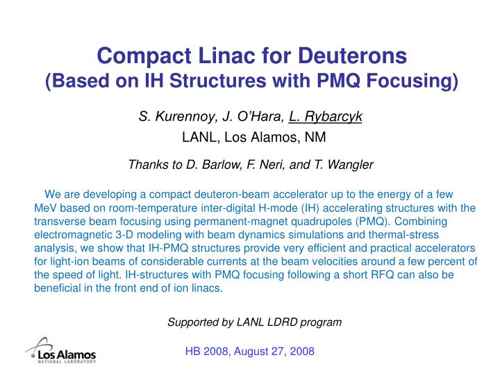
Compact Linac for Deuterons (Based on IH Structures with PMQ Focusing). LANL, Los Alamos, NM. Thanks to D. Barlow, F. Neri , and T. Wangler.

E N D
Compact Linac for Deuterons (Based on IH Structures with PMQ Focusing) LANL, Los Alamos, NM Thanks to D. Barlow, F. Neri, and T. Wangler We are developing a compact deuteron-beam accelerator up to the energy of a few MeV based on room-temperature inter-digital H-mode (IH) accelerating structures with the transverse beam focusing using permanent-magnet quadrupoles (PMQ). Combining electromagnetic 3-D modeling with beam dynamics simulations and thermal-stress analysis, we show that IH-PMQ structures provide very efficient and practical accelerators for light-ion beams of considerable currents at the beam velocities around a few percent of the speed of light. IH-structures with PMQ focusing following a short RFQ can also be beneficial in the front end of ion linacs. S. Kurennoy, J. O’Hara, L. Rybarcyk Supported by LANL LDRD program HB 2008, August 27, 2008
Introduction • Applications in homeland defense would benefit from deuteron beams of energy 4 MeV with the peak current of 50 mA and duty factor of 10%. • Can be done with a 4-MeV RFQ. • The higher energy part of the RFQ (β≥ 0.03) is not an efficient accelerator. • Alternative accelerating structures for 1 to 4 MeV (0.033 ≤ β ≤ 0.065): • IH (Interdigital H-resonator) structure operating in the TE11(0) (dipole) mode. • CH (Cross-bar H-resonator) structure operating in the TE21(0) (quadrupole) mode, same as RFQ. Multi-spoke cavities. • DTL (Drift-Tube Linac) – the classical structure for low-energy proton acceleration in TM010 (monopole) mode. • Quarter-wave (l/4) or half-wave (l/2) resonators, independently fed and phased, as used in low-energy superconducting heavy-ion accelerators. • Restrictions: • Room-temperature structures only (mobile applications). • Velocity range 0.033 ≤ β≤ 0.065 (lower limit - trade-off). • Frequency ~200 MHz. HB 2008, August 27, 2008
Structure comparison Reference: H. Podlech, LINAC04, p.28; U. Ratzinger, CAS 2000 Fig.1: Effective shunt impedance of low-energy accelerating structures versus β. The blue horizontal bars represent the existing IH-structures. HB 2008, August 27, 2008
Structure comparison Typical parameters of low-energy accelerating structures. † Estimated average value of Z for SNS RFQ is 2.6 MΩ/m; Z decreases as β-2 along the RFQ length. * T1 = LANSCE 201.25-MHz DTL tank 1, proton energy 0.75-5.39 MeV (T. Wangler, RF Linacs, p.99). ► λ/4 resonators are good in SC but not competitive with IH/CH at RT (high wall losses). DTL and especially H-mode accelerating structures are much more efficient than RFQ for β = 0.03-0.1, but, unlike the RFQ, they do not provide the beam focusing. If transverse focusing in H-structures can be achieved without significant reduction of Zeff, they would be the best choice. HB 2008, August 27, 2008
Transverse focusing options for H- & DTL-cavities • Magnetic quads inside DT, like in DTL, either EM or PMQ. Pro – established. Cons – not very efficient at low β; can be difficult for small DTs. Increasing DT reduces Zeff. • Split tanks – implement focusing between tanks. Pro – flexible scheme. Cons – reduces Zeff, requires RF power distribution, matching, increases length. • Insert quad triplets inside the tank, as done at GSI. Pro – established. Con – reduces Zeff due to the increased cavity length. • Provide transverse electric quadrupole focusing inside the tank. For CH – e.g., 4-vane insertions. For IH and DTL – split electrodes with fingers (V. Teplyakov; D. Swenson: RFID, RFD). Pro – efficient focusing at low β. Con – R&D needed, decreases Zeff. 5. Alternative-phase focusing(APF). Pro – Zeff is only slightly reduced, cons – low current limit, small longitudinal acceptance. Fig. 2: GSI IH-cavity with quad triplets (3). Reference: U. Ratzinger, NIM A464 (2001) 636. We propose to use PMQ inside the small DT in H-structures to preserve their high accelerating efficiency. HB 2008, August 27, 2008
MWS modeling of H- and DTL cavities – 1 Structure comparison at β = 0.034 (ra = 0.5 cm). E0 = 2.5 MV/m, f = 201.25 MHz * no optimization (values can be improved by changing the DT transverse dimensions and shape) IH IH with vanes CH DTL HB 2008, August 27, 2008
MWS modeling of H- and DTL cavities – 2 Structure comparison at β = 0.065 (no optimization). E0 = 2.5 MV/m, f = 201.25 MHz * The aperture radius here is 0.75 cm; the DT dimensions are adjusted to reduce max power density IH IH with vanes CH with small vanes DTL HB 2008, August 27, 2008
MWS modeling - optimizing H-cavities At β = 0.034 IH IH with vanes IH with mod vanes, small DT diameter ZT2 = 294.2 MΩ/m ZT2 = 346.2 MΩ/m (+) ZT2 = 745.8 MΩ/m (!) HB 2008, August 27, 2008
Beam dynamics TRACE 3-D. Parameters: I = 50 mA, β= 0.034 (1 MeV D) IH1-3: PMQ in every 3rd DT (B′=200 T/m, Lq=2 cm); rms ε= 0.2 π mm·mrad. Such PMQs are feasible! (Courtesy of Dave Barlow) xyz-matching between RFQ-H and H-DTL is feasible (F. Neri) Phase advance per period x: σ=33°, σ0=56°; y: σ=34°, σ0=56° Beam size: rmax = 4.3 mm. HB 2008, August 27, 2008
Beam dynamics 2 TRACE 3-D:I = 50 mA; norm εrms= 0.2 π mm·mrad; PMQ B′=200 T/m, Lq=2 cm. Focusing structure FnODnO: IH1-(n+1) = PMQ in every (n+1)th DT Table: Phase advances per focusing period and beam sizes for β= 0.034 IH1-5 should be excluded – beam stability The same exercise for β= 0.065: already IH1-4 is out. Longer DTs – more options. Overall, IH1-3 appears to be the best choice. NPMQ = 1/3 Nmax – cost reduction! HB 2008, August 27, 2008
EM properties of IH structures Regular IH structures with vanes & narrow gaps (g/Lc = 0.15). Shunt impedance of regular IH structures with narrow gaps versus βg. Transit-time factor of regular IH structures (defined by βg) versus beam velocity β. HB 2008, August 27, 2008
EM properties of IH structures - 2 Regular IH structures with vanes & narrow gaps (g/Lc = 0.15): Emax becomes high ( > 1.8EK) at βg ≥ 0.05. Maximal electric field in regular IH structures with narrow gaps versus βg. Surface loss power (100% duty) in regular IH structures with narrow gaps versus βg. HB 2008, August 27, 2008
IH Deuteron Accelerator 1 to 4 MeV: • The total number of IH cells ≤ 40 (19-20 periods): • either gradually increasing cell lengths (the cell length Lc = βλ/2), • or a three-step design that includes only cells with βg = 0.04, 0.05, 0.06. The cavity length is below 1.5 m (E0 = 2.5 MV/m; φ = -30°). • Required RF power (201.25 MHz): • CW: ≤ 25 kW cavity loss + (50 mA · 3 MV = 150 kW) in the beam; • at 10% duty: ≤ 3 kW cavity + 15 kW beam ≤18 kW average. • gives IOT option for RF + Transverse beam focusing with PMQs inside DTs. If PMQs are needed only in 1 out of 3 DTs, the structure effective shunt impedance can be increased even further by making empty DTs smaller. + Cooling with water channels inside vanes (not in DTs!) -- a simple and attractive scheme. Compact and efficient RT deuteron linac HB 2008, August 27, 2008
IH-structure improvement options • Increase the gap length between DTs by making the DTs shorter – • reduces Emax for a fixed gradient. • Especially attractive option at βg ≥ 0.05; LDT > Lq = 2 cm limits the gap width: • g/Lc= 0.25, 0.35, 0.45 for βg = 0.04, 0.05, 0.06 Maximal electric field (left) and shunt impedance (right) in regular IH structures versus g/Lc. HB 2008, August 27, 2008
Regular IH structures with wider gaps Surface current distribution in the IH structures with identical DTs and wider gaps: βg = 0.04, g = 0.25Lc (left), βg = 0.05, g = 0.35Lc (center), and βg = 0.06, g = 0.45Lc (right). HB 2008, August 27, 2008
IH-structure improvement options • Reduce the outer radius of empty DTs in IH1-n structures – • increases shunt impedance IH1-3 structure for βg = 0.034 with different transverse sizes for DT with (rout = 13 mm) and without PMQs (rout = 9 mm). Here g = 0.15Lc; ZshT2 = 370 MΩ/m (vs 347), but Emax! HB 2008, August 27, 2008
IH-structure improvement options 3. Combine 1 & 2: wider gaps and slim empty DTs in IH1-n structures – increases shunt impedance while keeping acceptable Emax. Modified IH1-3 structure for βg = 0.04 with large DT with PMQ (rout = 14 mm) and slim DT without PMQ (rout = 7 mm). Here g/Lc = 0.397 & 0.6; ZshT2 = 712 MΩ/m, Emax = 18.5 MV/m. HB 2008, August 27, 2008
IH structures with wider gaps – Etr on axis! The field asymmetry in IH was recognized long time ago. Mitigation – non-concentric bulges on the slim DTs [CERN (LINAC3) and GSI (HLI and HSI)]. Price – reduced Zsh (~15-20%); Emax is up by 50%. Other mitigation options are also possible, e.g. slanted DT ends. HB 2008, August 27, 2008
IH structures with wider gaps – Etr mitigation Electric fields in IH structures (left); with asymmetric bulges (center); with slanted ends (right): field arrows in the vertical symmetry plane (top, log scale), and on-axis fields (bottom). No bulges: reduced Zsh (~15-20%); Emax is up by 50%. Bulges Δ = 2 mm: δ = 3°. But Zsh ↓ 20%; Emax ↑ 50%. Slanted ends: <δ> = 0. Zsh ~↑ but Emax ↑ > 50%. No bulges: δ = 9.6°. HB 2008, August 27, 2008
Engineering analysis • A procedure to transfer surface-loss power data calculated by MWS to finite-element (FE) engineering codes COSMOS and ANSYS: • MWS fields are extracted not exactly at the cavity surface points but with a small offset into the cavity along the normal to each FE out of the FE center point. • This helps avoiding errors in the surface fields due to hexahedral MWS meshes as well as due to FE central points located inside the convex metal walls. • Temperature distribution in regular IH structures with water cooling in vanes for the nominal 10% duty: • Water 22°C, 2-m/s flow. Tmax (red) is 34.2°C, Tmax (blue) is 23.1°C. • No outside cooling is needed here. • DT vertical displacements for 10% duty are 30 and 40 μm – below the typical manufacturing tolerances. The important result – PMQ temperatures can be kept low with the vane cooling – confirms the IH-PMQ RT concept feasibility. HB 2008, August 27, 2008
Low-β RT Accelerating Structures: Summary • H-mode room-temperature accelerator structures are very efficient at the beam velocities from 0.03c to 0.065c. • They provide an attractive (compact, efficient) alternative to the RFQ deuteron accelerator from 1 to 4 MeV. • IH-structures with vanes appear to be the best: the most efficient, easy to fabricate, and easy to cool. • Total RF power requirements for an IH-cavity based 50-mA deuteron accelerator from 1 to 4 MeV are below 200 kW peak and 20 kW average. • Beam dynamics envelope simulations show that the beam transverse focusing with PMQ is feasible. • H-mode structures can be useful for the LANSCE linac upgrade: replace the aging DTL front-end. HB 2008, August 27, 2008
Conclusions The room-temperature RF accelerating structures based on H-mode resonators with the PMQ transverse beam focusing – which would follow a short, low-energy RFQ – appear to be an effective and feasible option for the beam velocities in the range of a few percent of the speed of light. They compare favorably to the usual DTL and RFQ structures with respect to their efficiency, compactness, ease of fabrication, and, likely, overall cost. • Future plans. • - Continue development of the room-temperature H-mode structures with PMQ focusing to achieve a balance of the structure efficiency, beam quality, and thermal management: iterations of • electromagnetic modeling (whole tank, end cells, …), • beam dynamics (multi-particle simulations: MWS fields → Parmela), • detailed engineering thermal-stress analysis. • - Cold model. • - PMQs (1-2). HB 2008, August 27, 2008
References: • S. Kurennoy, L. Rybarcyk, and T. Wangler, “Efficient Accelerating Structures for Low-Energy Light Ions,” PAC’07, Albuquerque, NM, p. 3824 (2007). • S. Kurennoy, Technical notes AOT-ABS: 07-032, 08-008, 08-017, LA-UR-08-03795, Los Alamos, 2008 • S. Kurennoy et al, “IH Accelerating Structures with PMQ Focusing for Low-Energy Light Ions,” EPAC08, Genoa, Italy, THPP026, p. 3431 (2008). HB 2008, August 27, 2008