Objectives and Thresholds for Effective Acquisition Program Management in Defense Systems
310 likes | 420 Views
This document outlines the objectives and thresholds essential for managing acquisition programs during their life cycle. It emphasizes the importance of cost, schedule, and performance parameters to ensure systems are affordable, timely, and operationally effective. The Program Manager (PM) is tasked with refining these objectives based on operational requirements and program maturation. The distinctions between "objectives" and "thresholds" are clarified, providing key insights into trade-offs allowed within defined limits. Additionally, it describes the systems engineering processes crucial for establishing and managing requirements effectively.

Objectives and Thresholds for Effective Acquisition Program Management in Defense Systems
E N D
Presentation Transcript
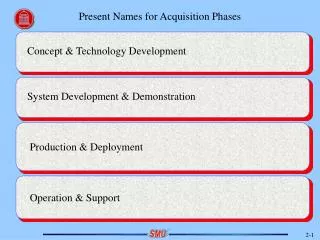
Present Names for Acquisition Phases Concept & Technology Development System Development & Demonstration Production & Deployment Operation & Support
Program Objectives and Thresholds Beginning at the inception of a new acquisition program, the PM shall propose objectives and thresholds for cost, schedule, and performance, that will result in systems that are affordable, timely, operationally effective, operationally suitable, and survivable. The PM shall refine these objectives and thresholds as the program matures, consistent with operational requirements.
Program Goals shall be Identified as Objectives and Thresholds Every acquisition program shall establish program goals – thresholds and objectives for the minimum number of cost, schedule, and performance parameters that describe the program over its life cycle.
Definition – Objective* The objective value is the value desired by the user, and the value the Program Manager tries to obtain. The objective value represents an incremental, operationally meaningful, time-critical, and cost-effective improvement to the threshold value of each program parameter. * Reference – DoD 5000.2-R, Chapter 1
Definition – Threshold* For performance, threshold shall mean the minimum acceptable value that, in the user’s judgment, is necessary to satisfy the need. For schedule and cost, threshold shall mean the maximum allowable value. If performance threshold values are not achieved, program performance may be seriously degraded, and the utility of the system may become questionable. If schedule threshold values are not achieved, the program may no longer be timely. If cost threshold values are not achieved, the program may be too costly, and the affordability of the system may become questionable. * Reference – DoD 5000.2-R, Chapter 1
Policy on Cost-Performance Trade-Offs* Cost, schedule, and performance may be traded-off within the “trade space” between the objective and the threshold without obtaining Milestone Decision Authority approval. Trade-offs outside the trade space shall require approval of both the Milestone Decision Authority and the Operational Requirements Document approval authority. Validated key performance parameters (KPPs) may not be traded-off without Requirements Authority approval. * Reference – DoD 5000.2-R, Chapter 1
Systems Engineering Process Engine Process Input Systems Analysis and Control Requirements Analysis Functional Analysis/Allocation Design Synthesis and Verification Process Output
Systems Engineering Process Inputs & Outputs • Inputs • Life- Cycle Needs • Product Objectives & Thresholds • Cost & Schedule Constraints • Best Practices & Standards Control Requirements • Outputs • Balanced System Solution • Decision Support Data • Product Specifications • Product Architectures Allocation Design
Systems Engineering Requirements Analysis Activities Process Input Systems Analysis and Control Requirements Analysis • Establish/refine operational and design requirements • Develop and refine system level functional and performance requirements and external interfaces • Provide traceability between user and design requirements Functional Analysis/Allocation Design Synthesis and Verification Process Output
Systems Engineering Functional Analysis/Allocation Activities Process Input Systems Analysis and Control Requirements Analysis Functional Analysis/Allocation • Define lower level functional and performance requirements • Establish traceability of requirements to higher/lower levels • Provide design and verification criteria to support integrated system design Design Synthesis and Verification Process Output
Systems Engineering Systems Analysis and Control Activities Process Input Systems Analysis and Control Requirements Analysis - Evaluate and select alternatives - Document design solutions - Implement risk management process - Maintain data and configuration management - Manage external and internal interfaces - Measure progress and structure reviews Functional Analysis/Allocation Design Synthesis and Verification Process Output
Key Systems Engineering Activities Include 1. Requirements Analysis- Throughout the acquisition process the program office shall work with the user to establish and refine operational and design requirements that result in the proper balance between performance and cost within affordability constraints. Requirements analysis shall be conducted iteratively with functional analysis/allocation to develop and refine customer objectives and requirements, define performance objectives and requirements, and provide traceability among user requirements and design requirements.
Key Systems Engineering Activities Include (Cont.) 2. Functional Analysis/Allocation - Functional analysis/allocation shall be performed iteratively to define successively lower level functional and performance requirements, including functional interfaces and architecture. Functional and performance requirements shall be traceable to higher level requirements. System requirements shall be allocated and defined in sufficient detail to provide design and verification criteria to support the integrated system design.
Requirements Characteristics • Unambiguous- Every Requirement Has Only One Interpretation • Complete - Includes All Significant Requirements, Functions, • Behaviors, Performance, Constraints, and • Interfaces • Verifiable - Cost-Effective Means Exist for People or Machines • to Check Product Against Requirements • Consistent - Requirements Not In Conflict • Modifiable - Requirements Are Easy to Change Completely and • Consistently • Correct - No Error Exists That Will Affect Design • Traceable - Origin of Requirement Is Clear • Design Free - Design Is Left to the Designer
Words that Don’t Provide Measurable Requirements Criteria • Fast • Should • May • Extremely • Under Most Conditions • As Appropriate • User Friendly • Should Fail Gracefully • Notes: • Requirements are problem statements. • A requirement has three parts – function, performance level, and verification means
Sample Weapons System RequirementsDatabase (common data) Number Type Statement Owner Development, Manufacturing, Verification, Deployment, Operations, Support, Training, or Disposal Text statement IPT (or name)
Sample Weapons System RequirementsDatabase (common data Cont. 1) WBS Parent Req. Child Req. Element Number Number Identifier
Sample Weapons System RequirementsDatabase (common data Cont. 2) Associated Trade Studies Related TPMs TPM Names Notes Trade Study Identifier Text
Sample Weapons System RequirementsDatabase (unique data by WBS) • Development: Cost, Schedule (for Hardware, Software, Facilities, Data, or Materials); Weight, Space, Power, Cooling (for Hardware) • Manufacturing: Primary Technology, Alternate Technology • (Availability, Cost, Risk) • Verification: Method, Description, Date • Operations: Performance Threshold, Performance Objective • Support: MTBF, Inspection Cycle, Spares Investment $, • Support Equipment Req. • Training: … • Disposal: ...
Sample Weapons System RequirementsDatabase (unique data by WBS Cont. 1) Software: - Performance (bits processed, speed, response time) - Constraints (standards, data format, language) - Interfaces (software, hardware, people) - Reliability (freq. of failure, severity of failure, recovery of failure) - Supportability (diagnostics, portability)
Key Engineering Activities Include(Cont.) 3. Design Synthesis and Verification - Design synthesis and verification activities shall translate functional and performance requirements into design solutions to include: alternative people, product and process concepts and solutions, and internal and external interfaces. These design solutions shall be in sufficient detail to enable verification that requirements have been met. The verification of the design shall include a cost-effective combination of design analysis, design modeling and simulation, and demonstration and testing. The verification process shall address the design tools, products and processes.
Example Summary of Verification Results Requirement – Diagnostics software will verify equipment operational readiness and fault detect and isolate problems to the cockpit panels/switches/indicators and LRU interfaces without user intervention after initiation. Verification Method – Demonstration Verification Requirement – Demonstrate that diagnostics software is capable of fault detection and isolation of problems for the Software Maintenance Maintenance Facility functional areas without user intervention. Summary of Verification Results – End-to-end functional component tests isolated faults down to the board level. A “test all components” option was executed which did not require user intervention. Note – Verification objectives are a good level to “talk to” in the Summary of Verification Results.
Key Systems Engineering Activities Include(Cont.) 4. Systems analysis and Control - System analysis and control activities shall be established to serve as a basis for evaluating and selecting alternatives, measuring progress, and documenting design decisions. This shall include: a. The conduct of trade-off studies among requirements (operational, functional and performance), design alternatives and their related manufacturing, testing and support processes, program schedule and life-cycle cost at the appropriate level of detail to support decision making and lead to a proper balance between performance and cost.
Key Systems Engineering Activities Include(Cont.) b. The establishment of a risk management process to be applied throughout the design process. The risk management effort shall address the identification and evaluation of potential sources of technical risks based on the technology being used and its application, risk mitigation efforts, and risk assessment and analysis. Technology transition criteria shall be established as part of the overall risk management effort.
Key Systems Engineering Activities Include(Cont.) c. A configuration management process to control the system products, processes and related documentation. The configuration management effort includes identifying, documenting, and verifying the functional and physical characteristics of an item, recording the configuration of an item, and controlling changes to an item and its documentation. It shall provide a complete audit trail of decisions and design modifications.
Key Systems Engineering Activities Include(Cont.) d. An integrated data management system to capture and control technical data and technical manuals, provide data correlation and traceability among requirements, designs, decisions, rationale, and other related program planning, status and reporting such as work breakdown structure, support configuration procedures, and serve as a ready reference for the systems engineering effort.
Key Systems Engineering Activities Include(Cont.) e. The establishment of performance metrics to provide measures of how well the technical development and design are evolving relative to what was planned and relative to meeting system requirements in terms of performance, risk mitigation, and cost.
See System Life Cycle with Reviewson Page 101 of Systems Engineering Fundamentals
The “V” Model:Decomposition & Integration Requirements Functional Design Integration Acceptance Produce analysis allocation and verification and deploy ASR SRR SFR PDR CDR SVR PCA SRR SDR SSR PDR CDR TRR FCA PRR FQR PCA System requirements Fully Integrated System Hardware, Software, Ops Procedures System verification Subsystem requirements: HWCIs CSCIs Subsystem integration and verification Integrated HWCIs, CSCIs Configuration Item Requirements CI Integration and verification Each CI Each Component, assembly, procedure HW assembly and CSC integration and verification Ops and Support Hardware Assemblies Software Components Hardware parts and processes Computer Software Units Each unit Unit integration and verification
Definitions from Systems Engineering Fundamentals System Engineering An interdisciplinary engineering management process that evolves and verifies an integrated, life-cycle balanced set of system solutions that satisfy customer needs. Systems Engineering Process A top-down comprehensive, iterative and recursive problem solving process, applied sequentially through all stages of development, that is used to: a. Transforms needs and requirements into a set of system product and process descriptions (adding value and more detail with each level of development). b. Generates information for decision makers, and c. Provides input for the next level of developments.