Download
1 / 46
460 likes | 607 Views
Explore the impact of stress and pore fluid pressure on rock failure through a virtual rock deformation experiment. Learn from Andersonian faulting principles and the concept of failure envelopes. Delve into the significance of fracking, shale drilling, and seismic activity related to deep injection wells.

E N D
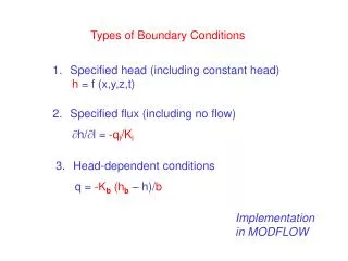
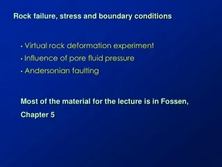
Rock failure, stress and boundary conditions • Virtual rock deformation experiment • Influence of pore fluid pressure • Andersonian faulting Most of the material for the lecture is in Fossen, Chapter 5
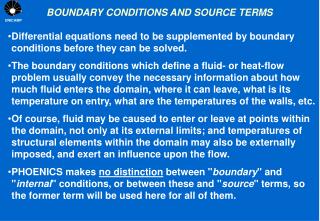
Failure envelope: created by a series of physical experiments where stresses are varied until the sample fractures. Each experiment is represented by a single point on the graph
Virtual Rock Deformation Experiment s1 s3 s1
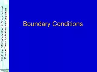
Determining the Failure Envelope sc = 0.29sn + 60 MPa f sc = 0.29sn + 60 MPa f f = 16 tan f = 0.29 s0 = 60 MPa sc = 0.29sn + 60 MPa
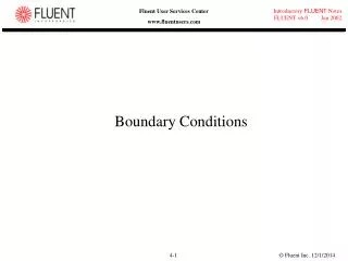
Predicting Failure Run 5: s3= 250 MPa; at what s1 fracture occur?
Predicting Failure Run 5: s3= 200 MPa; at what s1 fracture occur?
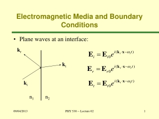
Compressive (+) vs tensile (-) stress • What is the minimum stress in this case?
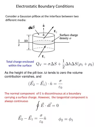
Failure envelope derived from increasing stresses on a rock sample until it fractures As shown previously, we can change the stress state by increasing or decreasing the principle stresses relative to one another, or change their orientation relative to the plane they are acting on. But we can change the internal stress as well (internal stresses act outward). If we increase internal stress, this decreases mean stress and brings the sample closer to failure. Internal stress is usually related to pore fluid pressure. In the oil and gas industry, this is fracking Effective stress is equal to the principle stresses minus the pore fluid pressure
Fracking and it’s impact… Marcellus, Bakken shales. Brittle, organic rich shales with low initial permeability (though Marcellus is jointed). Huge reserves of gas and oil, changing the USA’s need to import foreign oil. Big geopolitical implications. Lots of money to be made. Cheap hydrocarbons drive a growing economy. Lowering of carbon footprint by replacing coal with natural gas.
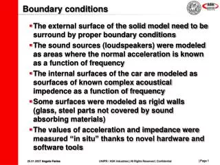
Drilling in sensitive areas, especially towns and cities. Noise, rigs seen as an eyesore. But drilling is short-lived and companies often cover rigs. Fear of contamination from fracking fluids, particularly groundwater. At issue is the connectivity between the shale source rocks and shallower levels where groundwater exists. Casing the borehole is important and potential problem if done incorrectly. Faults may provide connections between the surface and shallower levels. Earthquakes. Deep injection wells cause earthquakes to occur by changing the stress state in the source rocks. Causes existing faults to slip, can generate Mw 6.0 in places like Oklahoma. How to deal with legal issues?
Andersonian faulting What is it based on? How can it be used to infer stresses?
( ( Y = mX + b sc sn sn Assumptions for Andersonian Faulting • Coulomb brittle failure - no pre-existing faults
Normal stress (s1 , s2,s3) Assumptions for Andersonian Faulting • No shear stress exists at the Earth’s surface • One principal stress rotates to be normal to the surface, • s1 , s2,ors3 must be perpendicular to the surface • The remaining two principle stresses are horizontal
Principle stresses • Principal stresses are normal stresses only
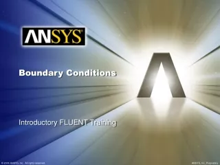
Conjugate Faults (both formed in the same stress field) Most simply - two fault planes that intersect to form a straight line Perhaps more typical - two fault surfaces that intersect to form a line Acute angle - < 90° angle (~60) Obtuse angle - > 90° angle (~120) Acute Obtuse
s1 bisects the acute angle • s2 is parallel to intersection of faults • s3 bisects the obtuse angle
In - class exercise: Determine the type of fault depending on the orientation of the conjugate faults seen below
The face is vertical and oriented east-west. What type of faults are these, and what is the trend and plunge of each principle stress. What is the strike and dip of each fault, and what is the trend and plunge of the slickenlines that would form on each fault surface.
The face is horizontal and north is up on the page. What type of faults are these, and what is the trend and plunge of each principle stress. What is the strike and dip of each fault, and what is the trend and plunge of the slickenlines that would form on each fault surface.
The face is vertical and strikes north-south. What type of faults are these, and what is the trend and plunge of each principle stress. What is the strike and dip of each fault, and what is the trend and plunge of the slickenlines that would form on each fault surface.
Print following six slides - each conjugate fault image should have it’s own block diagram to help visualize the orientation of each pair relative to NSEW…
The face is vertical and oriented east-west. What type of faults are these, and what is the trend and plunge of each principle stress. What is the strike and dip of each fault, and what is the trend and plunge of the slickenlines that would form on each fault surface. It helps to draw the two conjugate faults in 3D perspective
The face is horizontal and north is up on the page. What type of faults are these, and what is the trend and plunge of each principle stress. What is the strike and dip of each fault, and what is the trend and plunge of the slickenlines that would form on each fault surface. It helps to draw the two conjugate faults in 3D perspective
The face is vertical and strikes north-south. What type of faults are these, and what is the trend and plunge of each principle stress. What is the strike and dip of each fault, and what is the trend and plunge of the slickenlines that would form on each fault surface. It helps to draw the two conjugate faults in 3D perspective
For each of the three examples, draw in the orientation of the faults on the block diagram, label the sense of movement on them, and state whether they are normal, thrust or dip slip
Borehole breakouts indicate that some (weak) faults create their own half space.
Stresses across plate boundaries Stress fields from: Ridge push, buoyant mantle at spreading ridge, followed by subsidence as oceanic crust thickens, cools and subsides Passive margin, gravity – material moves from shelf to slope to abyssal deep Back arc thrust belt, shortening Arc, buoyant – magmatism + high heat flow Accretionary wedge, shortening, offscraping of upper oceanic crust Downgoing slab –subduction is really the process of sinking
India-Eurasia stresses are complicated! E-Quakes + deformation results from thrusting at frontal suture; lateral escape within Tibet – mostly to the east. Minor extension in hot, thick crust of Tibet. So how should faults be oriented? (strike and dip) Thrusts Strike slip Normal
India-Eurasia stresses Complex! E-Quakes + deformation results from thrusting at frontal suture; lateral escape within Tibet – mostly to east. Minor extension in hot, thick crust of Tibet. So how should faults be oriented? (strike and dip) Thrusts: E-W, dipping north along frontal Himalaya Strike slip: Conjugate, WNW-ESE, vert. + ENE-WSW, vert. Normal: EW, North and South
Class exercise in Google Earth (work in groups of 4) Locate major thrust faults along the leading edge of the frontal Himalaya. Label with 10 stick pins, list lat, long and turn in. Make a sketch map of thrusts. Draw a topographic profile across the frontal Himalaya, and identify thrust related uplifts. (Here they are mostly folds). Locate major strike slip faults in Tibet, especially along its northern edge. Label with 10 stick pins, list and turn in. Sketch map of a big part of central Tibet. What is the sense of slip on the fault you mapped? Question, why are the traces of the strike slip faults so linear?
Class exercise in Google Earth (work in groups of 4) Locate major thrust faults along the leading edge of the frontal Himalaya. Label with 5 stick pins, list lat, long and turn in. Make a sketch map of thrusts. Draw a topographic profile across the frontal Himalaya, and identify thrust related uplifts. (Here they are mostly folds). Locate a major strike slip faults in Tibet, especially along its northern edge and in eastern Tibet (i.e. the Altyn Tagh or Kun Lun Faults). Label with 5 stick pins, list and turn in. Question, why are the traces of the strike slip faults so linear? Following slide goes up on board to help everyone locate the large strike slip faults.