Download
1 / 94
940 likes | 966 Views
This chapter covers error detection and correction in data link layers, addressing single-bit and burst errors, redundancy, forward error correction, coding schemes, and block coding techniques like Hamming Distance. Learn the process of error detection using codes.

E N D
Chapter 10 Error Detection and Correction
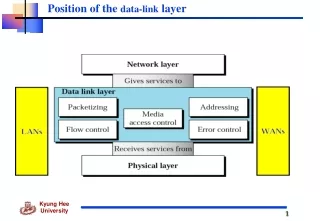
Note Error Detection and Correction • Data can be corrupted during transmission. • Some applications require that errors be detected and corrected. • Error Detection and Correction are implemented at the data link layer and the transport layer of the internet model
10.1 INTRODUCTION Let us first discuss some issues related, directly or indirectly, to error detection and correction. Topics discussed in this section: Types of ErrorsRedundancyDetection Versus CorrectionForward Error Correction Versus RetransmissionCoding Modular Arithmetic
Type of Errors(cont’d) • Single-Bit Error • In a single-bit error, only 1 bit in the data unit has changed.
Type of Errors(cont’d) • Burst-Bit Error • A burst error means that 2 or more bits in the data unit have changed. • The length of the burst is measured from the 1st corrupted bit to the last corrupted bit. • Some bits in between may not have been corrupted.
Redundancy • The central concept in detecting or correcting errors is Redundancy. • Instead of repeating the entire data stream, a shorter group of bits may be appended to the end of each unit. → This technique is called Redundancy. • These extra bits are discarded as soon as the accuracy of the transmission has been determined. To detect or correct errors, we need to send extra (redundant) bits with data.
Error Detection Vs Correction • Error detection • looking only to see if any error has occurred. • Error correction • Need to know the exact number of bits that are corrupted and more importantly, their location in the message. • The correction of errors is more difficult than the detection.
Forward Error Correction Vs Retransmission • Forward Error Correction • is the process in which the receiver tries to guess the message by using redundant bits. • Retransmission • is a technique in which the receiver detects the occurrence of an error and asks the sender to resend the message.
Coding • Redundancy is achieved through various coding schemes. • Coding schemes : Block coding and Convolution coding. • The sender adds redundant bits through a process that creates a relationship between redundant bits and the actual data bits. • The receiver checks the relationships between the two sets of bits to detect or correct the errors.
Coding Figure 10.3 The structure of encoder and decoder In this book, we concentrate on block codes; we leave convolution codes to advanced texts.
Modular Arithmetic • In modulo-N arithmetic, we use only the integers in the range 0 to N −1, inclusive. • We define an upper limit, called a Modulus N. • We then use only the integers 0 to N −1, inclusive.
Modulo-2 Arithmetic • Adding 0+0=0 0+1=1 1+0=1 1+1=0 • Subtracting 0-0=0 0-1=1 1-0=1 1-1=0 Figure 10.4 XORing of two single bits or two words
10.2 BLOCK CODING In block coding, we divide our message into blocks, each of k bits, calleddatawords. We add r redundant bits to each block to make the length n = k + r. The resulting n-bit blocks are calledcodewords. Topics discussed in this section: Error DetectionError CorrectionHamming Distance Minimum Hamming Distance
Block Coding Figure 10.5 Datawords and codewords in block coding
Block Coding Example 10.1 The 4B/5B block coding discussed in Chapter 4 is a good example of this type of coding. In this coding scheme, k = 4 and n = 5. As we saw, we have 2k = 16 datawords and 2n = 32 codewords. We saw that 16 out of 32 codewords are used for message transfer and the rest are either used for other purposes or unused.
BLOCK CODING - Error detection • If the following two conditions are met, the receiver can detect a change in the original codeword. • The receiver has (or can find) a list of valid codewords. • The original codeword has changed to an invalid one. Figure 10.6 Process of error detection in block coding
BLOCK CODING - Error detection Example 10.2 Table 10.1 A code for error detection (Example 10.2) Let us assume that k = 2 and n = 3. Table 10.1 shows the list of datawords and codewords. Later, we will see how to derive a codeword from a dataword. Assume the sender encodes the dataword 01 as 011 and sends it to the receiver. Consider the following cases: 1. The receiver receives 011. It is a valid codeword. The receiver extracts the dataword 01 from it.
BLOCK CODING - Error detection Example 10.2 (continued) 2. The codeword is corrupted during transmission, and 111 is received. This is not a valid codeword and is discarded. 3. The codeword is corrupted during transmission, and 000 is received. This is a valid codeword. The receiver incorrectly extracts the dataword 00. Two corrupted bits have made the error undetectable. Table 10.1 A code for error detection (Example 10.2)
BLOCK CODING - Error detection Table 10.1 A code for error detection (Example 10.2)
Note BLOCK CODING - Error detection An error-detecting code can detect only the types of errors for which it is designed; other types of errors may remain undetected.
BLOCK CODING - Error Correction • In error correction, the receiver needs to find (or guess) the original codeword sent. • We need more redundant bits for error correction than for error detection. Figure 10.7 Structure of encoder and decoder in error correction
BLOCK CODING - Error Correction Example 10.3 Let us add more redundant bits to Example 10.2 to see if the receiver can correct an error without knowing what was actually sent. We add 3 redundant bits to the 2-bit dataword to make 5-bit codewords. Table 10.2 shows the datawords and codewords. Assume the dataword is 01. The sender creates the codeword 01011. The codeword is corrupted during transmission, and 01001 is received. First, the receiver finds that the received codeword is not in the table. This means an error has occurred. The receiver, assuming that there is only 1 bit corrupted, uses the following strategy to guess the correct dataword.
BLOCK CODING - Error Correction Example 10.3 (continued) 1.Comparing the received codeword with the first codeword in the table (01001 versus 00000), the receiver decides that the first codeword is not the one that was sent because there are two different bits. 2. By the same reasoning, the original codeword cannot be the third or fourth one in the table. 3. The original codeword must be the second one in the table because this is the only one that differs from the received codeword by 1 bit.The receiver replaces 01001 with 01011 and consults the table to find the dataword 01. Table 10.2 A code for error correction (Example 10.3)
BLOCK CODING - Error Correction Table 10.2 A code for error correction (Example 10.3)
BLOCK CODING - Hamming Distance • Hamming distance between two words (of the same size) is the number of difference between the corresponding bits. • We show the Hamming distance between two words x and y as d(x,y) • The Hamming distance can easily be found if we apply the XOR operation ( )on the two words and count the number of 1s in the result.
BLOCK CODING - Error Correction Example 10.4 Let us find the Hamming distance between two pairs of words. 1. The Hamming distance d(000, 011) is 2 because 2.The Hamming distance d(10101, 11110) is 3 because
BLOCK CODING - Minimum Hamming Distance • The minimum Hamming distance is the smallest Hamming distance between all possible pairs in a set of words. • We use dmin to define the minimum Hamming distance in a coding scheme.
BLOCK CODING - Minimum Hamming Distance Example 10.5 Find the minimum Hamming distance of the coding scheme in Table 10.1. Solution We first find all Hamming distances. The dmin in this case is 2. Table 10.1 A code for error detection (Example 10.2)
BLOCK CODING - Minimum Hamming Distance Example 10.6 Find the minimum Hamming distance of the coding scheme in Table 10.2. Solution We first find all the Hamming distances. The dmin in this case is 3. Table 10.2 A code for error correction (Example 10.3)
BLOCK CODING - Hamming Distance • Three parameters • A coding scheme C is written as C(n,k) with a separate expression for dmin . • For example, we can call our first coding scheme c(3,2) with dmin =2 and our second coding scheme c(5,2) with dmin =3. • Hamming distance and Error • The Hamming distance between the received cordword and the sent codeword is the number of bits that are corrupted during transmission. • For example : 3 bits are in error and the hamming distance between the two is d(00000, 01101) = 3
BLOCK CODING - Minimum Distance for error detection • To guarantee the detection of up to s errors in all cases, the minimum Hamming distance in a block code must be dmin = s + 1. • so that the received codeword does not match a valid codeword.
BLOCK CODING - Minimum Distance for error detection Example 10.7 The minimum Hamming distance for our first code scheme (Table 10.1) is 2. This code guarantees detection of only a single error. For example, if the third codeword (101) is sent and one error occurs, the received codeword does not match any valid codeword. If two errors occur, however, the received codeword may match a valid codeword and the errors are not detected. • one error : 101 100 (does not match any valid code) • Two errors : 101 000 (errors are not detected) Table 10.1 A code for error detection (Example 10.2)
BLOCK CODING - Minimum Distance for error detection Example 10.8 Our second block code scheme (Table 10.2) has dmin = 3. This code can detect up to two errors. Again, we see that when any of the valid codewords is sent, two errors create a codeword which is not in the table of valid codewords. The receiver cannot be fooled. However, some combinations of three errors change a valid codeword to another valid codeword. The receiver accepts the received codeword and the errors are undetected. Table 10.2 A code for error correction (Example 10.3)
BLOCK CODING - Minimum Distance for error detection Figure 10.8 Geometric concept for finding dmin in error detection
BLOCK CODING - Minimum Distance for Error Correction Figure 10.9 Geometric concept for finding dmin in error correction
Note BLOCK CODING - Minimum Distance for Error Correction To guarantee correction of up to t errors in all cases, the minimum Hamming distance in a block code must be dmin = 2t + 1.
BLOCK CODING - Minimum Distance for Error Correction Example 10.9 A code scheme has a Hamming distance dmin = 4. What is the error detection and correction capability of this scheme? Solution This code guarantees the detection of up to three errors(s = 3), but it can correct up to one error. In other words, if this code is used for error correction, part of its capability is wasted. Error correction codes need to have an odd minimum distance (3, 5, 7, . . . ).
10.3 LINEAR BLOCK CODES Almost all block codes used today belong to a subset calledlinear block codes. A linear block code is a code in which the exclusive OR (addition modulo-2) of two valid codewords creates another valid codeword. Topics discussed in this section: Minimum Distance for Linear Block CodesSome Linear Block Codes
Linear Block Codes Example 10.10 Let us see if the two codes we defined in Table 10.1 and Table 10.2 belong to the class of linear block codes. 1. The scheme in Table 10.1 is a linear block code because the result of XORing any codeword with any other codeword is a valid codeword. For example, the XORing of the second and third codewords creates the fourth one. 2. The scheme in Table 10.2 is also a linear block code. We can create all four codewords by XORing two other codewords. Table10.1 Table10.2
Minimum Distance for Linear Block Codes • The minimum Hamming distance is the number of 1s in the nonzero valid codeword with the smallest number of 1s.
Minimum Distance for Linear Block Codes Example 10.11 In our first code (Table 10.1), the numbers of 1s in the nonzero codewords are 2, 2, and 2. So the minimum Hamming distance is dmin = 2. In our second code (Table 10.2), the numbers of 1s in the nonzero codewords are 3, 3, and 4. So in this code we have dmin = 3. Table10.1 Table10.2
Linear Block Codes-Simple parity-Check Code • In Simple parity-check code, a k-bit dataword is changed to an n-bit codeword where n=k+1. • The extra bit, called the parity bit, is selected to make the total number of 1s in the codeword even or odd. • This code is a single-bit error-detecting code; it cannot correct any error. A simple parity-check code is a single-bit error-detecting code in which n = k + 1 with dmin = 2.
Minimum Distance for Linear Block Codes Table 10.3 Simple parity-check code C(5, 4)
Minimum Distance for Linear Block Codes Figure 10.10 Encoder and decoder for simple parity-check code
Minimum Distance for Linear Block Codes Example 10.12 Let us look at some transmission scenarios. Assume the sender sends the dataword 1011. The codeword created from this dataword is 10111, which is sent to the receiver. We examine five cases: 1. No error occurs; the received codeword is 10111. The syndrome is 0. The dataword 1011 is created. 2. One single-bit error changes a1 . The received codeword is 10011. The syndrome is 1. No dataword is created. 3. One single-bit error changes r0 . The received codeword is 10110. The syndrome is 1. No dataword is created.
Minimum Distance for Linear Block Codes Example 10.12 (continued) 4. An error changes r0 and a second error changes a3 . The received codeword is 00110. The syndrome is 0. The dataword 0011 is created at the receiver. Note that here the dataword is wrongly created due to the syndrome value. 5. Three bits—a3, a2, and a1—are changed by errors. The received codeword is 01011. The syndrome is 1. The dataword is not created. This shows that the simple parity check, guaranteed to detect one single error, can also find any odd number of errors.
Note A simple parity-check code can detect an odd number of errors.
LINEAR BLOCK CODES - Two-dimensional parity Check Code • In Two-dimensional parity-check code, the data code is organized in a table (rows and columns). • In fig.10.11, the data to be sent, five 7bit bytes, are put in separate rows. • For each row and each column, 1 parity-check bit is calculated. • The whole table is then sent to the receiver, which finds the syndrome for each row and each column. • As Fig.10.11 shows, the two-dimensional parity check can detect up to three errors that occur anywhere in the table.