Download
1 / 20
200 likes | 214 Views
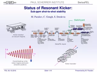
Status of Resonant Kicker: Sub-ppm shot-to-shot stability. M. Paraliev, C. Gough, S. Dordevic. Kicker chamber (in-vacuum magnet). Switchyard. SwissFEL layout. A. t. Current build-up in the kicker magnet and bunch extraction positions. Kicker resonator. Overview. SwissFEL layout.

E N D
Status of Resonant Kicker:Sub-ppm shot-to-shot stability M. Paraliev, C. Gough, S. Dordevic Kicker chamber (in-vacuum magnet) Switchyard SwissFEL layout A t Current build-up in the kicker magnet and bunch extraction positions Kicker resonator
Overview SwissFEL layout Kicker 1 Kicker 2 Septum Kicker system key parameters Beam energy – 3 GeV Bunch separation – 28 ns Total deflection angle – 1.8 mrad Number of Kickers – 2 Deflection angle error – 80 ppm Total magnets length – 1.5 m Line field integral – 10 mT.m Deflecting current – 590 App Switchyard
Resonant Kicker Concept Athos I L/2 Linac 2 Aramis L/2 C Illustration of bunches separation using a resonant deflecting system L Resonant technology • No RL transient slope • No skin effect slope • Lower voltages (HV is enclosed in vacuum) • Solid state technology • Compact design • New driver technology • Complex amplitude measurement (ppm) • Demanding synchronization • Resonance frequency control C 56 ns LLctrl Driver Simplified electrical circuit Vacuum 500 Ap-p 1st bunch I (B) t Ref.: M. Paraliev, C. Gough, “Development of High Performance Electron Beam Switching System for Swiss Free Electron Laser at PSI”, Proc. IPMHVC 2012, p. 691, San Diego, CA, USA, 2012 Resonance build-up 2nd bunch
Beam trajectory Switch Yard The two kickers K1 and K2 (together with the accompanying dipoles D1, D2 and D3) provide about 1.8 mrad deflection. Adding the quads contribution the effective deflection is reduced to about 1 mrad. Beam separation at the entrance of the septum magnet is nominal 10 mm. Field regions and beam trajectory in SwissFEL switch yard Color rectangles represent the corresponding field regions Q – Quadrupole magnet Kx – Kicker magnet Dx – Dipole magnet S – Septum magnet
Beam trajectory Kickers’ region The kickers K1 and K2 deflect both bunches (“straight” and “deflected”) vertically but in the opposite direction. Deflecting both beams results in 50% reduction of the required magnetic field strength (respectively the current in the magnets) The three dipole magnets get the “straight” beam back to its original trajectory and increase deflection angle of the deflected beam. • Beam trajectory in the kickers’ region • Color rectangles represent the corresponding field regions • Q – Quadrupole magnet • Kx – Kicker magnet • Dx – Dipole magnet
Modes of operation “Separation” In “Normal” bunches separation mode, the bunches are sent to the two beamlines. The numbers above the magnets’ centers (dashed lines) represent the relative deflecting strength of the particular magnet. Asymmetric configurations are also possible. “Normal” separation mode An “Alternative” separation mode makes possible to keep the simultaneous operation of the two beamlines but using only two “accompanying” dipole magnets. The mode could be used for dipoles debugging. “Alternative” separation mode
Modes of operation “One beamline only” “Aramis only” mode “Athos only” mode In “One beamline only” modes both bunches are sent to only one of the beamlines. The resonant kickers are off. The alternative “Aramis only” mode could be used to evaluate the stability of the DC “accompanying” dipole magnets. “Aramis only” alternative mode Ref.: M. Paraliev, C. Gough, S. Dordevic, H. Braun, “High Stability Resonant Kicker Development for the SwissFEL Switch Yard”, 36th International Free Electron Laser Conference FEL 2014, MOP039, Basel, Switzerland, 2014
Amplitude stability Shot-to-shot (feedback off) Averaged RMS Stability PMS1 = 8.0·10-7 Stability PMS3 = 8.1·10-7 • Noise floor PMS1 = 6.2·10-7 • Noise floor PMS3 = 6.4·10-7 • Stability Kicker* = 5.0·10-7 • Kicker system stab.* = 3.5·10-7 • * Calculated Two measurement systems working simultaneously Precision measurement system 1 (PMS1) Precision measurement system 3 (PMS3) Shot-to-shot stability of 100 consecutive pulses with feedback off (rep. rate 50 Hz)
Amplitude stability With feedback “PMS1”, “PMS3” and “Full Range” have same scale. PMS3 PMS1 Full Range Stability degraded with time – why?
Amplitude stability Mains synchronization irregularity “PMS1”, “PMS3” and “Full Range” have same scale. PMS3 PMS1 Full Range Irregular pulsing degrades stability due to the finite charging slope (~0.5 ppt/ms) of the main power module storage capacitors. (Tough compromise between precision and speed)
Amplitude stability Frequency effects (resonator tuning) “PMS1” and “PMS3” have same scale. (ppm) Full Range PMS1 PMS3 At resonance the dominant instability source is the mechanical vibration of the lid (thin sheet is used during testing for convenience) At ~13 ppm above resonance the detuning and the q-factor modulation cancel out and minimizing the amplitude instability.
Phase stability RF Mixer and ADC based measurements 5 mdeg 24 mdeg ADC based measurement (averaged phase, pulse-to-pulse deviation) RF Mixer measurement (instantaneous phase, intra-pulse measurement) The fast ADCs (16 bit, 250 MHz) of the Full Range amplitude measurement system digitize the sine wave. The phase and the amplitude of the kicker’s current are measured using digital synchronous detection. The values are averaged during the RF pulse to increase precision. The signal processing is done by dedicated fast FPGA (Virtex-6) that sends the results to EPICS. The ADC based phase measurement is limited by the ground vibration to ~5 mdeg. The RF mixer based measurement gives an upper limit of the instantaneous phase noise ~24 mdeg.
Phase stability Considering multi bunch operation Worst case (highest derivative) phase driven amplitude instability estimation: 180° (on-crest) operation, (two bunches separation) - negligible - OK 45° operation** (four bunches separation) - 62 (300) ppm – probably OK 90° operation** (three or five bunches separation) - 87 (420) ppm – high! **possible future operation modes
Expert panel (to be implemented) Kicker electronics RF power modules Driver Temperature controlled precision voltage references and regulators Self diagnostics module programmable voltage regulator 20 bit resolution Synchronization Power supplies • High stability RF power modules (~ 5 kW peak @ 17.86 MHz) • Operational for only ~100 us @ 100 Hz - low average power ~ 50 W. • Four RF power modules in parallel. • Precision programmable (20 bit resolution) voltage regulator. • Self diagnostics module – device status (internal temperatures, interlocks, and etc.) • 4U rack mount water cooled chassis • Designed and built in PSI.
Kicker electronics Expert panel (To be implemented) Precision amplitude measurement system Low noise difference matrix amplifier/detector 10 bit 40 Ms/s ADC and FPGA module Balancing unit and input limiter Power supply (Bottom side) Precision 20 bit programmable current source Temperature controlled reference voltage source DC/DC converters, regulators, filters and self diagnostics module (Bottom side) • Resolution ~0.3 ppm, noise floor ~0.6 ppm, range ± 150 ppm • Fast recovery (<10 ns) analogue input limiter – withstanding 10000% overload • High stability programmable (20 bit resolution) current source - 2 A (for balancing) • Self diagnostics module – device status (internal temperatures, supply voltages and etc.) • 2U rack mount water cooled chassis • Designed and built in PSI.
Kickers Mechanicaldesign The tanks for the three identical systems are delivered. Vacuum tank The resonators are in production. There were delays mainly due to some difficulties associated with the ceramic details’ brazing. The parts should be ready next month. Resonator
Lambertson septum Mechanicaldesign Solenoid Iron core Air St. steel plate Longitudinal field (0.001Hz) Vacuum Deflected beam 3D simulation model Straight beam Alu ring for high frequency field components suppression Transverse field (higher frequency suppression) • Half-in-vacuum design • Deflection 35 mrad • High frequency field components suppression • Designed in PSI.
Conclusion • A novel concept for bunches separation using a resonant kicker magnet was developed and evaluated. A prototype of the resonant kicker was designed and built together with dedicated driver and monitoring system. • A slow feedback SW application (C code) controls the system using EPICS channel access protocol. • Since the shot-to-shot stability is crucial for this novel concept to work, the stability of the prototype system was extensively evaluated: • Shot-to-shot amplitude stability (feedback ON): ~1.5 ppm rms • Shot-to-shot amplitude stability (feedback OFF): ~0.8 ppm rms • Shot-to-shot phase stability: RF pulse average ~5 mdeg ( instantaneous <24 mdeg) • Shot-to-shot phase driven amplitude instability: <0.1 ppm • The achieved stability levels open possibilities for separating more bunches in future. Thank you for yourattention!
Additional material Derivation