Download
1 / 41
410 likes | 519 Views
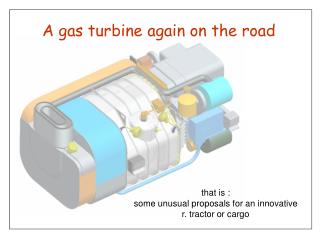
A gas turbine again on the road. that is : some unusual proposals for an innovative r. tractor or cargo. FOREWORD.

E N D
A gas turbine again on the road that is : some unusual proposals for an innovative r. tractor or cargo
FOREWORD It is known that, soon after the 2° Great War, many big road vehicles constructors begun to test gas turbine, as possible substitute of the more heavy and cumbersome reciprocating (diesel) engine. The tests went on for almost one half of century but, inspite of this perseverance, our power plant, so successful in aeronautical applications, proved to be very disappointing on the road, staying unsolved many troubles : - low thermal efficiency high fuel consumption; - lack of motor retarding weak exhaust brake; - low elasticity turbo lag; - remarkable encumbrance of the exhaust system; - pollution, because of the huge bulk of smoke to deal. We can assume that many of these drawbacks may be charged, in more or less ratio, with a peculiarity of our engine : starving of air. In fact a lot of air is requested to dilute the combustion gas to avoid an overheating of blades : all this means an overlabour of the compressor which needs a power no less than double the net work. Moreover the need of a heat exchanger, necessary to recover the heat latent into exhaust gas, limits the possibility to increase the feeding air pressure which, to improve thermal efficiency, would be as important as it is supercharging for diesel engines. To solve all these problems are here proposed some expedients, the first of them aims at sparing comburent air, saving up diluting flow : this target will be reached by means of two solutions, working in compound. 3
1st : a massive recourse to E.G.R. (Exhaust Gas Recirc.) system, with an effective precleaning and cooling plant, giving us, at the same time, a sound lowering of combustion gas temperature (and therefore NOX emissions). 2nd : the fell down of combustion gas heat will go on by means of a crossing through a heat exchanger, placed no more downstream the turbines, but before them; the warmth in excess is took away by the air coming from the compression / aftercooling set and is sent directly to the combustion chamber with full thermal recovery. To get the wanted results our device must have a rather low thermal efficiency (no more than 40%), so having quite restricted dimensions and good streamlined behaviour, to not obstruct the flow of hot fluid. Because of the hight temperature of the comburent air and the absence of dilution, it has devised a redesign of the combustion liner, as further detailed. This file collects some other suggestions, aiming at several targets, all conceived to renew the heavy commercial vehicle : lighter kerbweight, better grip and roadholding power, bifuel supplying, and moreover many other improvements, as illustrated in the following pages. All this will be detailed into the next chapters, structured according these items : Engine …………………………………………………………………………………….…………. Page 6 Driveline ……………………………………………………………………………………………… Page 24 Chassis : frame + suspensions + steering system ……………………………………………… Page 29 Cab …………………………………………………………………………………………………... Page 36 Sketches …………………………………………………………………………………………….. Page 39 Contacts ……………………………………………………………………………………………… Page 41 4
Some approx. data (top range engine) : ENGINE TYPE : gas turbine dual shaft; COMPRESSOR : centrifugal flow, 2 stage (single spool) driven by 2 stage axial turbine; Pressure ratio : ~13.5:1 at 42,000 RPM. Mass air flow : ~0.6 Kg/sec (only 1/8° in comparison with a traditional G.T. of the same power) POWER TURBINE : 2 stage axial with fixed inlet guide vanes (no V.G.T.) Expected max. rating ~ 550 KW at 27,000 RPM. Expected max. torque ~ 3000 Nm (at stall). MAX. TEMPERATURE : Before turbine : 850°C Exhaust : 550°C SPECIFIC FUEL CONSUMPTION : ~ 200 gr. / KW / HR. (average) OVERALL WEIGHT : ~350 Kg. MAIN DIMENSIONS : height : ~598 mm width : ~735 mm lenght : ~1420mm 5
ENGINE Dimensions (mm) Cab heating duct Fuel pump Exhaust duct ~598 ~735 Oil filler ~1420 Air compressor EGR duct - cleaner Elect.contr. unit Air inlets Elect.starter / generator Exhaust brake control Fuel filter Main case EGR control Antilag control EGR cooler 6 Combustion chamber Intercooler
ENGINE (section) 21 10 11 12 16 17 9 1 2 3 4 7 5 6 8 13 14 15 18 19 20 1. Feeding air inlet - 2. Cooling air inlet - 3. Cooling fan - 4. EGR cooler - 5. Oil cooler 6. Intercooler - 7. Scroll - 8. Compressor shaft - 9. 1st stage compressor - 10. 2nd stage compressor 11. Compressors turbines - 12. Power turbines - 13. Heat exchanger - 14. Combustion gas duct 15. Powershaft - 16. EGR intake - 17. Exhaust duct - 18. Reduction box - 19. Oil sump 20. Cab heating duct - 21. Centrifugal oil filter 7
Some details Cooling fan guide vanes EGR valve Oil cooler Air condit. condenser EGR cooler Intercooler Cooling air inlet Front bearing (compressor) Cooling fan Feeding air inlet Strut 8
Starter-booster valve (antilag) Starting position Bypassed air sent directly to the combustion chamber. Minimum RPM (idle) As above, but a little share is stored, to give a following boost. Medium-Max RPM Full flow sent to intercooler and distrib. collector. 11
120°C 12
Full power Distributor valves opened Main valve closed Exhaust brake Distributor valves closed Main valve opened 13
Exhaust brake set Pressure driven disc controlling the which covers exit ports. sliding cursor FULL POWER POSITION Return leaf springs EXHAUST BRAKE POSITION Distributing collector Discovered air exit ports, creating an aerodynamic retarder on the power turbine last stage. 15
Gasfire set (A) Feeding-cooling air flow 700°C Combustion chamber 150°C Feeding air which cools combustion gases. Metallic net layers to cool combustion gas duct. 16
Gasfire set (A) Combustion chamber 700°C 1400°C The feeding air enters into the combustion liner creating a tidy swirl which wraps the fuel spray. 17
Gasfire set (B) Throttle control Bifuel nozzle Fuel filter 700°C Ignition plug 850°C 1400°C Electric wires Oil pipes Air cond. pipes 18
Heat exchanger (A) Uniflow fluids way (to avoid overheating) Single items Full set 19
Heat exchanger (B) Leant edges Welded shells Through the minigrooves a leak of air cools the inlet edge. 20
Combustion gas ducts Hopper Intermediate insulated partition Annular-inverted collector 21
Reduction box with power tranfert (cruise speed) and hydrodynamic retarder (twin set) Coupling gears Hydrodynamic retarder Hydraulic joint Compressor reduction gears Free wheel Powershaft reduction gears Powershatfs 22
Gears set and auxiliaries Fuel pump Electronic Control Unit Service air compressor (rototraslating blades or “G lader”) Centrifugal oil filter Fuel accumulator Throttle control Fuel booster Elect.starter / generator Air conditioning compressor Oil pumps Oil filter and pipes 23
Gear box (16 speeds, alternatively engaged) Sliding front wheel mesh High range shaft Inlet power shafts (elastic joints) REAR Hydr. PTO (Fast) FRONT Reverse 4th 3rd 2nd 1st Twin clutches Intermediate differential Reverse Splitters Hydr. PTO (Slow) Low range shaft The sequence of speeds engaging progresses alternating from one range shaft to the other one. 25
Gear box section and front wheels drive Sliding front wheel mesh Coaxial shafts REAR FRONT 385/55 R22.5 Intermediate differential Steering box 26
Rear bogie Brake control unit Hub reduction spur gears Diffential between rear wheels Hypoid bevel set Rear tie rod Cardanic joints 27
Front drive Pneumatic control engage (connected with drive selection) Swivel Front wheel sliding mesh (automat. disconnected when idle) 28 3
CHASSIS 29
Frame – Suspensions - Auxiliaries Crossmember incorporating a half shell of the diffential box. Rear bogie suspension controlled by fifth wheel Cab heating duct Cold accumulator box Gas bottles (LPG) (4x) Gas bottles (LPG) (2x) Fuel tank Batteries Indipendent suspension (LDS spring system) Gas pressure reductor Foot brake control 31 Compressed air bottles
Indipendent suspensions (details) Air spring Auxiliary bottle Inbuild damper controlling Caster angle Single arm Rubber bearings Stump axle Fuel tank Antiroll bar (3x) 32
Ajustable antiroll bar Sliding sleeve (splined inside) Empty vehicle Spline Return spring (max resilience) Long bar Short bar Pneumatic control inlet (connected with pneum. susp. system) Full charged vehicle Spline (max rigidity) 33
Steering Controls Steering box Electric power assisted system Adjustable pedal set Foldable side dashboard Tie rod Bent manoeuvring handle Bowden cables steering system Foldable manoeuvring handle incorporating a shunting knob (Forward – Stop - Reverse) Heel holder pedal which, sliding, controls exhaust brake and hydr. retarder 34
Spare wheel arrangement 1 3 2 Sliding and hanging reels Screw bar Hook-handle to lower and to rise the wheel 35
CAB 36
CAB (Air ways) Cooling air Feeding air Exhaust gas Dry cleaners Muffler-catalyzator housing Exhaust chimney Cab heating duct Double bottom 550°C 37
CAB (some details) LDS suspension system, governing cab rolling and pitching. Heating cab air inlet Hydr. Lock (activated by tilting pump) Side glasses cleaning drag (also foldable safety support) Foldable stairs 38
SKETCHES 39
SKETCHES 36 ft. 36 ft. 28T 32T 60T 40
Contacts February 2010 If you like to get more details, please apply to : Aldo RICCARDI Corso Francia, 54 10143 TORINO TO ITALY Phone no. +39.0114375895 (Sorry : no internet, no fax) For CAD informations : Michael COQUET Via IV Novembre, 11/C 10048 VINOVO (TO) ITALY Phone no. +39.3490800274 michael.coquet@tiscali.it (Modelled with Pro/Engineer Wildfire 2.0) 41