FIXTURE ASSEMBLY DOCUMENT
FIXTURE ASSEMBLY DOCUMENT. OP. ?0 OF ?00 PAGE 0? OF ??. Author: Brian Younce. X-Spot Lamp Socket Replacement Procedure. 1. !. Please keep all hardware and parts that are removed in a safe place for re-installation. 1.


FIXTURE ASSEMBLY DOCUMENT
E N D
Presentation Transcript
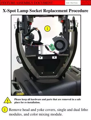
FIXTURE ASSEMBLY DOCUMENT OP. ?0 OF ?00 PAGE 0? OF ?? Author: Brian Younce X-Spot Lamp Socket Replacement Procedure 1 ! Please keep all hardware and parts that are removed in a safe place for re-installation. 1 Remove head and yoke covers, single and dual litho modules, and color mixing module.
2 3 4 Remove 7mm ground lug nut. 2 Carefully cut zip tie that secures wires to wire clamp. Open clamp and pull wires out. 3 Disconnect blue lamp wire connectors. 4
5 Once wires are free, route them through the tilt tube into the head. 5
6 Remove 7mm nut, pull wire routing clip free of mounting stud, and detach clip from lamp harness for later re-installation onto new lamp harness. Pull wire harness through grommet and out to the other side of the head. 6
7 7 Remove the 4 – 3mm socket cap screws that retain the wire harness half-clamps, then remove the 7mm hex nut that retains the 2 ground lugs.
8 8 Loosen the 2 lamp cap thumbscrews and remove lamp cap. Remove the lamp and allow lamp cap to hang freely.
9 10 10 Carefully disconnect the fan tach sensor wire from the sensor board and disconnect the fan wire connectors from each other. 9 10 Remove the 6 – 3mm socket cap screws that retain the rear vent/fan plate assy. Pull the fan plate off at this time.
11 ! Temporarily re-install the lamp cap. Remove the 2 - 3m socket cap screws used to retain the lamp reflector assy. and pull the assy. out. 11
12 12 Pull the lamp harness out through the lower grommet as shown. You are now ready to install your new lamp cap/harness!
13 13 After you have pulled the old lamp cap/harness assy. out, install the new lamp cap/harness as shown above. You may want to wait to install the lamp.
14 14 This step is the reverse of step 11 on page 8. Re-install the 2 – 3mm socket cap lamp reflector screws. Take care in routing the harness through the grommet while making sure the sheathing doesn’t get pinched or cut.
15 15 Be sure to leave a service loop as shown above to ensure that future lamp cap removal is easily achieved.
16 16 Route the harness up through the upper head grommet and re-install the wire harness half clamps using the 4 – 3mm socket cap screws and the ground lugs using the 7mm hex nut.
17 17 Install the wire clamp onto the new harness and mount it to the stud using the 7mm hex nut. At this time route the harness up to and through the tilt tube.
19 18 Re-install the fan and lamp vent plates using the 6 – 3mm socket cap screws. 18 Plug the fan tach sensor wire back into the sensor and reconnect the fan wire connectors. 19
20 21 22 20 Re-install the ground wires to the stud using the 7mm hex nut. Reconnect the blue lamp wire connectors – they are keyed to prevent incorrect connection. 21 22 Route the wires through the wire clip.
Re-install the single and dual litho modules, color mixing module, and the yoke and head covers. You are finished!