
Uploaded by
raya-waters
4 SLIDES
248 VIEWS
40LIKES
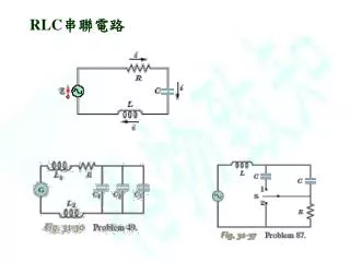
RLC 串聯 電路
DESCRIPTION
RLC 串聯 電路. 示波器 Ch1. 可變電阻. 函數產生器 範圍 ~kHz. A. 共振曲線半寬值比 (fractional half-width) =△ω / ω = △ f / f. 實驗 A :共振曲線. -. 改變頻率,記錄電流的大小,畫出曲線,找出共振頻率 ( f r ) 及半寬值。並找出 f 1 改變電阻值,重複前一步驟。. f 2. f r. f 1. 請將講義上的 f 1/2 均改為 f 1. -. f 2. f r. f 1.
Download
1 / 4
Download Presentation 
RLC 串聯 電路
An Image/Link below is provided (as is) to download presentation
Download Policy: Content on the Website is provided to you AS IS for your information and personal use and may not be sold / licensed / shared on other websites without getting consent from its author.
Content is provided to you AS IS for your information and personal use only.
Download presentation by click this link.
While downloading, if for some reason you are not able to download a presentation, the publisher may have deleted the file from their server.
During download, if you can't get a presentation, the file might be deleted by the publisher.
E N D
Presentation Transcript
示波器 Ch1 可變電阻 函數產生器 範圍 ~kHz A • 共振曲線半寬值比 (fractional half-width) =△ω / ω • =△f / f 實驗A:共振曲線 - 改變頻率,記錄電流的大小,畫出曲線,找出共振頻率(fr)及半寬值。並找出 f1 改變電阻值,重複前一步驟。 f2 fr f1
請將講義上的 f1/2均改為f1 - f2 fr f1
實驗B:觀察電阻、電容和電感,每兩者之間的相位差實驗B:觀察電阻、電容和電感,每兩者之間的相位差 示波器 Ch1 電阻請選共振曲線山比較高的那一個 示波器 Ch2 可變電阻 函數產生器 範圍 ~kHz 頻率選在共振頻率(fr)。 畫出示波器上所看到之二者波形(Dual)、李賽圖形(X-Y) ,由此判斷VR和VC的相位差,及畫出phasor。並和課本比較。(畫圖時請將橫軸刻度標示清楚) 示波器改接到電容和電感二端,重複前一步驟。 頻率改成非共振頻率(f1),重複前面幾個步驟。
More Related