Download
1 / 12
120 likes | 144 Views
Learn about the components of an IP packet, such as version, TTL, and checksum, to ensure proper data transmission. Explore the cooperation between layers through encapsulation and decapsulation. Vertical communication on routers is also covered. Gain insights into site connections and ISP networks.

E N D
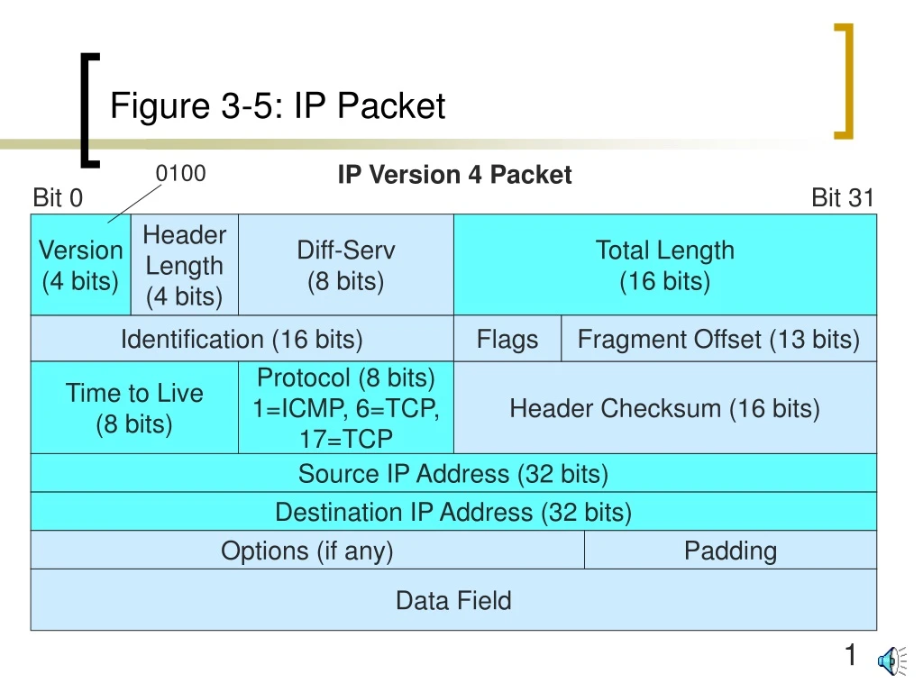
Figure 3-5: IP Packet 0100 IP Version 4 Packet Bit 0 Bit 31 Version (4 bits) Header Length (4 bits) Diff-Serv (8 bits) Total Length (16 bits) Identification (16 bits) Flags Fragment Offset (13 bits) Time to Live (8 bits) Protocol (8 bits) 1=ICMP, 6=TCP, 17=TCP Header Checksum (16 bits) Source IP Address (32 bits) Destination IP Address (32 bits) Options (if any) Padding Data Field
Figure 3-5: IP Packet • Version • Has value of four (0100) • Time to Live (TTL) • Prevents the endless circulation of mis-addressed packets • Value is set by sender • Decremented by one by each router along the way • If reaches zero, router throws packet away
Figure 3-5: IP Packet • Protocol Field • Identifies contents of data field • 1 = ICMP • 6 = TCP • 17 =UDP IP Data Field ICMP Message IP Header Protocol=1 IP Data Field TCP Segment IP Header Protocol=6 IP Data Field UDP Datagram IP Header Protocol=17
Figure 3-5: IP Packet • Header checksum to check for errors in the header only • Faster than checking the whole packet • Stops bad headers from causing problems • IP Version 6 drops eve this checking • Address Fields • 32 bits long, of course • Options field(s) give optional parameters • Data field contains the payload of the packet.
Figure 3-9: Layer Cooperation Through Encapsulation on the Source Host Application Process HTTP Message Encapsulation of HTTP message in data field of a TCP segment Transport Process HTTP Message TCP Hdr Encapsulation of TCP segment in data field of an IP packet Internet Process HTTP Message TCP Hdr IP Hdr
HTTP Message TCP Hdr IP Hdr DL Trlr HTTP Message TCP Hdr IP Hdr DL Hdr Figure 3-9: Layer Cooperation Through Encapsulation on the Source Host Internet Process Encapsulation of IP packet in data field of a frame Data Link Process Physical Process Converts Bits of Frame into Signals
Figure 3-9: Layer Cooperation Through Encapsulation on the Source Host Note: The following is the final frame for supervisory TCP segments: DL Trlr TCP Hdr IP Hdr DL Hdr
Figure 3-10: Layer Cooperation Through Decapsulation on the Destination Host Application Process HTTP Message Decapsulation of HTTP message from data field of a TCP segment Transport Process HTTP Message TCP Hdr Decapsulation of TCP segment from data field of an IP packet Internet Process HTTP Message TCP Hdr IP Hdr
HTTP Message TCP Hdr IP Hdr DL Hdr HTTP Message TCP Hdr IP Hdr DL Hdr Figure 3-10: Layer Cooperation Through Decapsulation on the Destination Host Internet Process Decapsulation of IP packet from data field of a frame Data Link Process Data Link Process Converts Signals into the Bits of the Frame
Figure 3-11: Vertical Communication on Router R1 A Internet Layer Process Router R1 Packet Port 1 DL Port 2 DL Port 3 DL Port 4 DL Decapsulation Frame PHY PHY PHY PHY • Notes: • Router R1 receives frame from Switch X2 in Port 1. • Port 1 DL process decapsulates packet. • Port 1 DL process passes packet to internet process. Switch X2
Figure 3-11: Vertical Communication on Router R1 B Internet Layer Process Router R1 Packet Port 1 DL Port 2 DL Port 3 DL Port 4 DL Encapsulation Frame PHY PHY PHY PHY • Internet process sends packet out on Port 4. • DL Process on Port 4 encapsulates packet in a PPP frame. • DL process passes frame to Port 4 PHY. Router 2
Packet Packet Packet Figure 3-12: Site Connection to an ISP Internet Backbone 1. Frame for This Data Link Site Network 2. Packet Carried in ISP Carrier Frame ISP Border Firewall 4. Data Link Between Site and ISP (Difficult to Attack) 3. Packet Carried in Site Frame ISP Router 5. Normally, Only the Arriving Packet is Dangerous—Not the Frame Fields