
ASSEMBLING THE PCB
E N D
Presentation Transcript
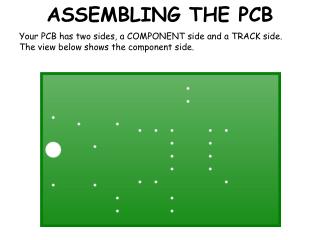
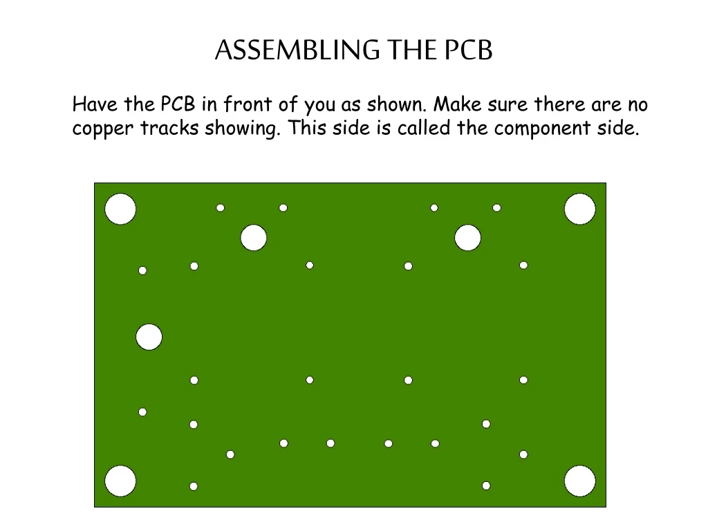
ASSEMBLING THE PCB Have the PCB in front of you as shown. Make sure there are no copper tracks showing. This side is called the component side.
ASSEMBLING THE PCB Insert the two 220ohm resistors. These can be either way round. Try to ensure they sit as close to the board as possible
ASSEMBLING THE PCB Next insert the two timing resistors. These will be either 10K, 22K or 47K depending on how fast you want the LED’s to flash.
ASSEMBLING THE PCB Next insert the two timing capacitors. It is important they are inserted the correct way round. Note the black stripes on the side of the capacitors, these denote the negative wire. NEGATIVE CONNECTION
ASSEMBLING THE PCB Now insert the two transistors. It is important the three wires are inserted correctly and not twisted. Take care not to heat the component with the soldering iron for too long.
ASSEMBLING THE PCB Next feed the two wires from the battery clip up through the 3mm hole and back into the 1mm holes as shown. This provides some strain relief for the wires to prevent them breaking.
ASSEMBLING THE PCB Finally repeat the wiring process with two pairs of coloured wire ready for soldering to the LED’s.